●Troubleshooting
85
7
Troubleshooting
Troubleshooting
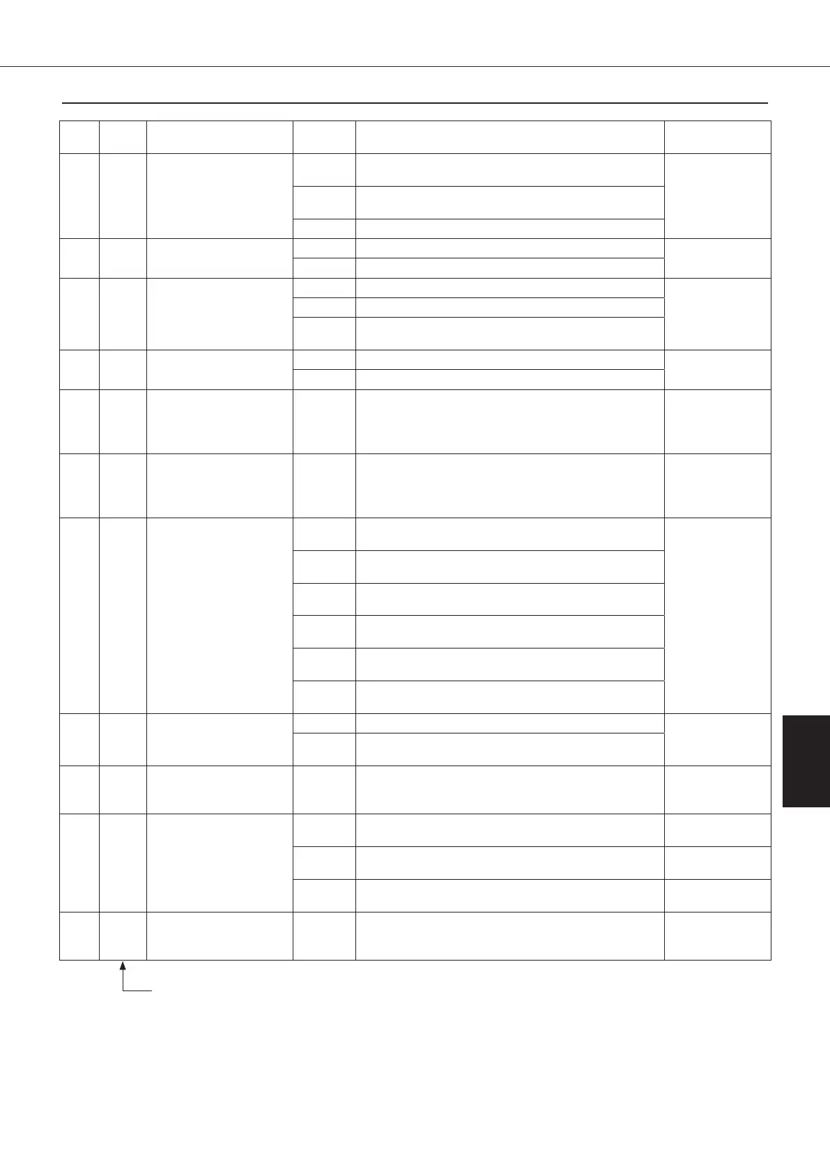
Alarm
code
Alarm
level
Malfunction Class Operating condition
Measure
(Page)
L5 2
Instantaneous
overcurrent of power
device
70
When compressor step-out is detected (within 3
minutes after startup).
P.101
71
When compressor step-out is detected (after 3
minutes after startup).
72 When an IPM error signal is detected.
L8 2 Compressor overload
70 When compressor step-out is detected.
P.102
71 When low voltage abnormality is detected.
L9 2
Faulty compressor
startup
70 The compressor does not rotate smoothly.
P.103
71
When single-phase open phase of the compressor is detected.
72
When two- or three-phase open phase or current
abnormality of the compressor is detected.
LA 2
Malfunction of power
device
70 When current abnormality is detected.
P.104
71 When voltage abnormality is detected.
LC 2
Malfunction of
transmission between
inverter CPU and
temperature control CPU
10, 11
When the transmission is not performed normally for
a period of given time or more.
P.105
U0 2 Shortage of refrigerant 10
①Command capacity ≧95%
② Condenser temperature - EE valve outlet
temperature ≦5℃
① and ② continue for a period of three minutes.
P.106
U1 1
Reverse phase/open
phase of power supply
or wire broken in fuse,
low voltage (power
supply voltage)
10
When reverse phase is detected in the power supply
circuit immediately after the power is turned on.
P.107
11
When L1 is detected in the power supply circuit
immediately after the power is turned on.
12
When L2 is detected in the power supply circuit
immediately after the power is turned on.
13
When L3 is detected in the power supply circuit
immediately after the power is turned on.
14
When single-phase open phase of L1, L2, or L3 is
detected during use.
15
When two-phase open phase of L1, L2, or L3 is
detected during use.
U2 2
Low voltage (inverter
main circuit DC voltage)
70 When the main circuit voltage is insufficient.
P.108
71
When the main circuit voltage does not rise due to
charging circuit failure.
U9 2
Malfunction of
transmission with slave
unit
10
When transmission between the master unit and the
slave unit is not performed normally for a period of
given time or more.
P.109
UH 2 System-related failure
10–13 EEPROM causes a failure.
Replace the
control board
70–72 Inverter control software error.
Replace the
inverter board
80–83 Temperature control software error.
Replace the
control board
UJ
1
or
2
Actuation of external
safety device
50–53
The protective device connected to the CN2 on the
control board is actuated.
P.110
Alarm level 1 … Pump OFF + Compressor (heater) OFF + Fan OFF
Alarm level 2 … Pump ON + Compressor (heater) OFF + Fan ON
*E3/E5 (Class: 50) : the fan stops at the same time.
(Notes) Emergency operation
・
In case of malfunction of room thermistor ……………… Emergency operation is enabled in operation mode 0, 1, 4, 6, or 9 (H1 warning display)
・
In case of malfunction of machine body thermistor …… Emergency operation is enabled in operation mode 0, 1, 3, 5, or 9
・
In case of malfunction of inlet oil thermistor …………… Emergency operation is enabled in operation mode 1, 5, 6, or 9 (JH warning display)
・
In case of malfunction of outlet oil thermistor …………… Emergency operation is enabled in operation mode 0, 3, 4, or 9
00_PB00540A_M10.indb 85 2023/08/09 12:59:05