157
●Miscellaneous Reference Data
10
Miscellaneous Reference Data
Miscellaneous
Reference Data
To use a ground leakage breaker, select an inverter-compatible type.
If the ground leakage breaker is not inverter-compatible, it may malfunction due to high-frequency noise of the inverter.
CAUTION
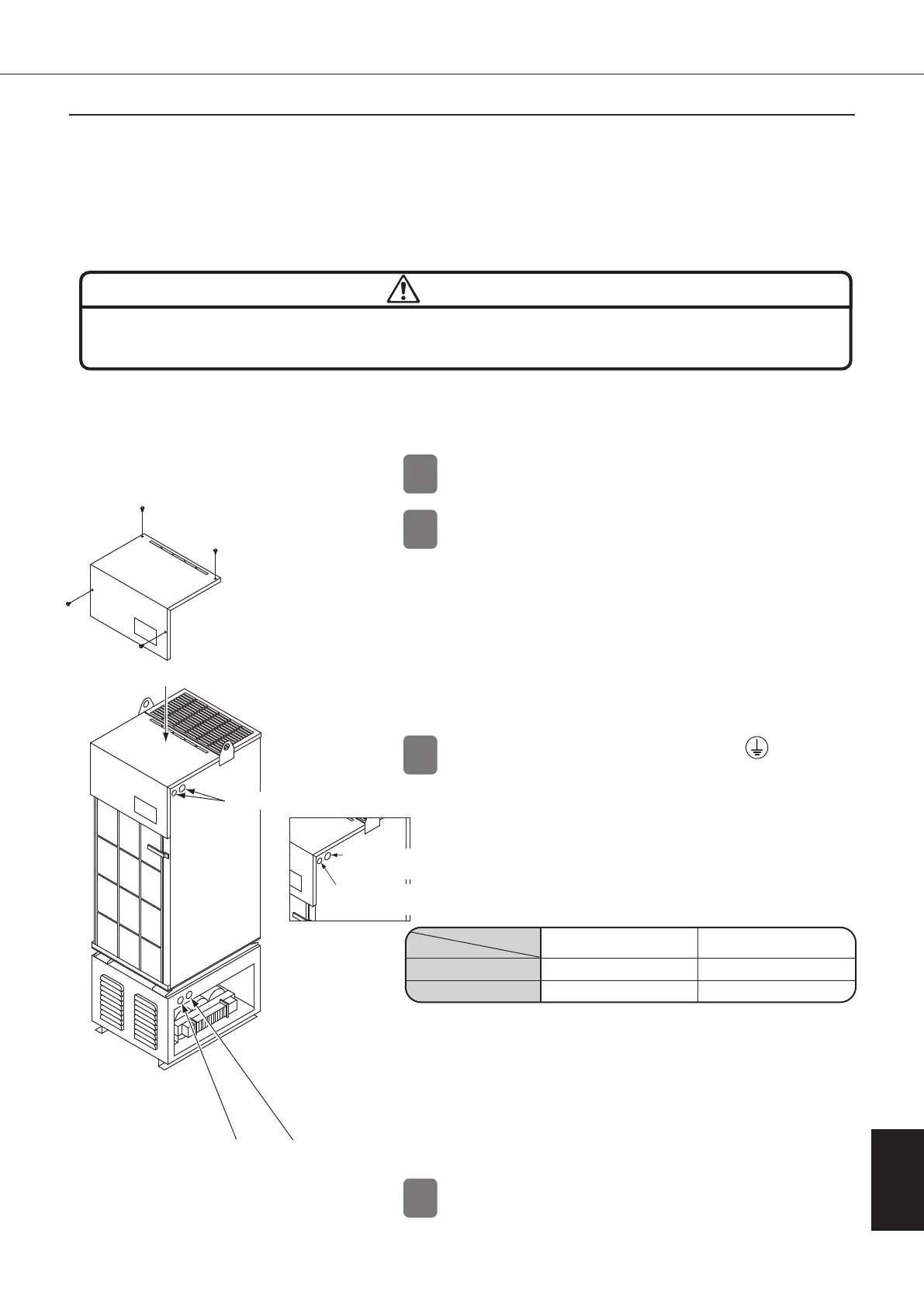
Remove the switch box cover mounting
screws, and remove the switch box cover.
1.
Insert the power cable into the power cable
insertion hole (φ28) in the side plate of the unit.
2.
Insert the remote control signal cable and
external output signal cable into the signal cable
insertion hole (φ22) in the side plate of the unit.
When using the different-voltage model (-048),
insert the power cable into the transformer box.
1.
Connect the ground cable to the (ground)
terminal.
Use green/yellow ground cable.
2.
Connect the power cable to the power supply
terminal block.
Connect the power cable to the breaker if
OILCON is supplied with breaker.
Secure the switch box cover mounting screws with 1N·m to
maintain the protection structure of the switch box.
For each wiring, use M4 or M5 coated round crimp-style terminal. (For
the crimp tool, use the specified tool.
Carry out the processing of the crimp-style terminal to prevent
short- circuits between phases.)
The tightening torque of the screw to the terminal block should
be 0.98 to 1.47N·m.
Carry out the processing of the wiring careful not to damage
the electric wire coating.
Fix the electric wire and the signal wire to the anchor mount
with tie wrap.
∗
Use conduits with IP54 or higher for wiring intake to allow the electric
component box to have a protective structure equivalent to IP54.
If the electric component box is affected by electrical noise, use
conduits or shielded cables. Allow a proper distance from the
potential noise source.
Re-mount the switch box cover, and fasten it
with the screws.
∗
The ground leakage circuit breaker must conform to IEC 60947-2, and the distance between the contacts must be more than 3 mm.
The Oil Cooling Unit is not equipped with a ground leakage circuit breaker. Be sure to mount a 3-pole ground leakage circuit
breaker (∗) exclusively for the Oil Cooling Unit to the main machine. For the breaker capacity, refer to the specifications of each
model (from page 10).
(Recommended product: Rated sensitivity current 15 mA or 20 mA)
1
2
3
4
When you remove the power cables, follow the instructions above in
reverse. (Default setting is breaker OFF.)
The cable size should conform to those listed below, or a larger size.
Cable type
Model/Series name
AKZ14A/32A/43A/56A series
UL1015 AWG#14 (equivalent to 2.0 mm
2
)
2.5 mm
2
(60245 IEC53/H05RR-F)
AKZ90A series
UL1015 AWG#12 (equivalent to 3.5 mm
2
)
4.0 mm
2
(60245 IEC53/H05RR-F)
UL cable
IEC/CENELEC cable
Standard model, -B, -C, -H, -T,
different-voltage (-046)
(2)(3)
Different-voltage
model (-048)
Signal cable insertion
hole (
φ
22)
Power cable insertion
hole (
φ
28)
Transformer box
Switch box
cover
Switch box cover
mounting screw
(1)(4)
Power cable insertion
hole (
φ
28)
Signal cable insertion
hole (
φ
22)
(2)(3)
4-2. Mounting a Ground Leakage Circuit Breaker
4-3. Wiring procedure
00_PB00540A_M10.indb 157 2023/08/09 12:59:27