116
7
Troubleshooting
Check
4
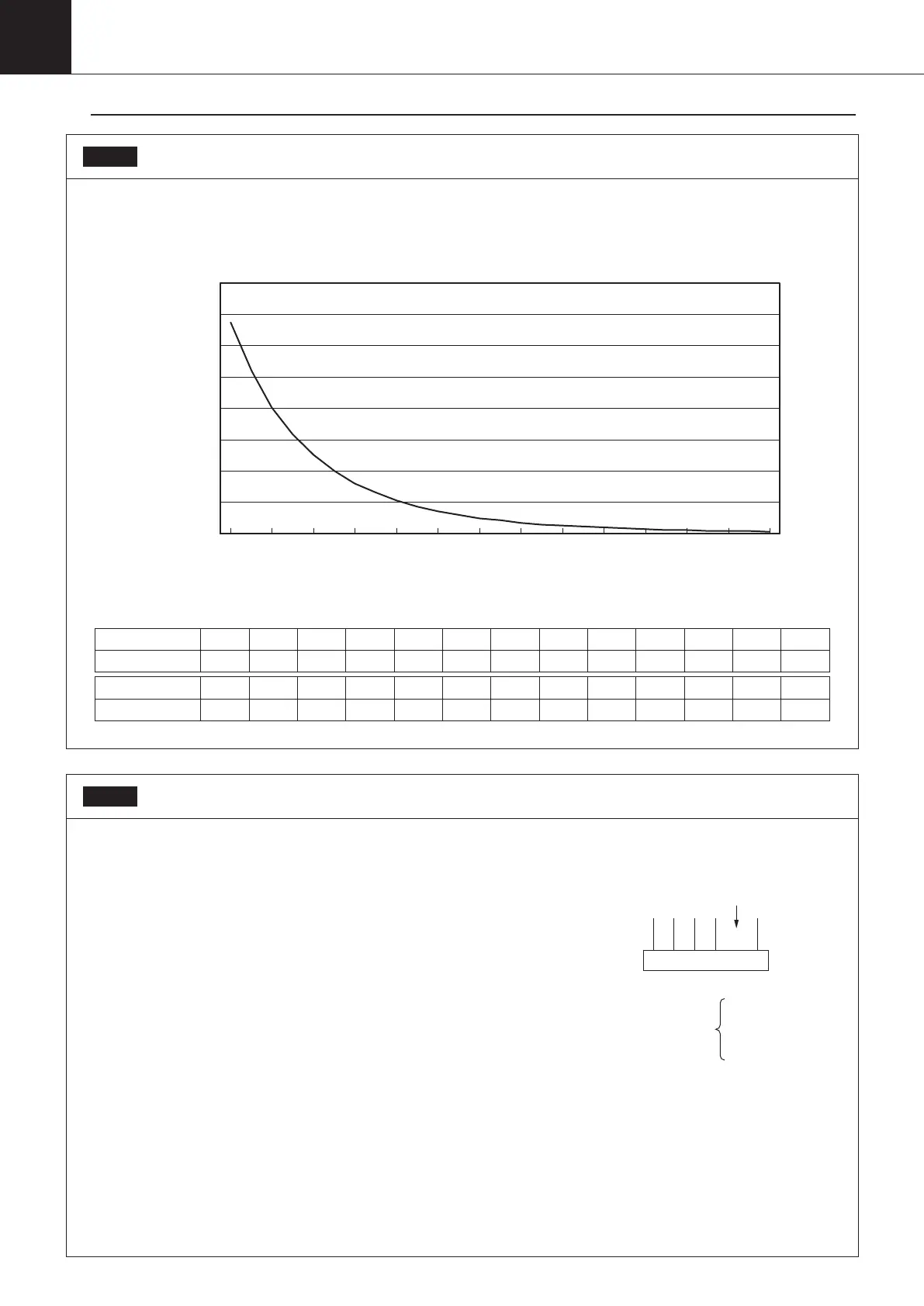
Check 1
Check the thermistor resistance value
Remove each thermistor and connector, and measure the resistance value of each thermistor with a tester.
The relationship between temperature and resistance during normal operation is as shown in the graph and table below.
Characteristics of thermistor
0.00
10.00
20.00
30.00
40.00
50.00
60.00
70.00
80.00
℃
0 10
1201101009080706050403020
Temperature (℃) 0 10 15 20 25 30 35 40 45 50 55 60 65
Resistance value (kΩ)
67.33 40.38 31.69 25.08 20.00 16.07 13.01 10.60 8.69 7.17 5.95 4.97 4.17
Temperature (℃) 70 75 80 85 90 95 100 105 110 115 120 125 130
Resistance value (kΩ)
3.51 2.98 2.54 2.17 1.86 1.61 1.39 1.21 1.06 0.92 0.81 0.72 0.63
Check 2
Check the motor operated valve
Check the motor operated valve according to the following items.
① Check if the motor operated valve connector is properly inserted
on the control board, and check the harness of the motor operated
valve coil against the connector number.
② Check if there is any rattling latch noise when the power supply is
turned off and then turned on again.
③ If there is no noise in ② above, remove the connector and check the
resistance of the motor operated valve coil.
*Normal motor operated valve coil resistance
Electronic expansion valve for main circuit (Y1E): 46 ± 4Ω (20℃)
Motor operated valve for hot gas (Y2E): 46 ± 3Ω (20℃ )
Harness : 5
WT YE OR BL RD
Empty
6-1
6-2
6-3
Check
00_PB00540A_M10.indb 116 2023/08/09 12:59:08