2
Standard Specifications
8
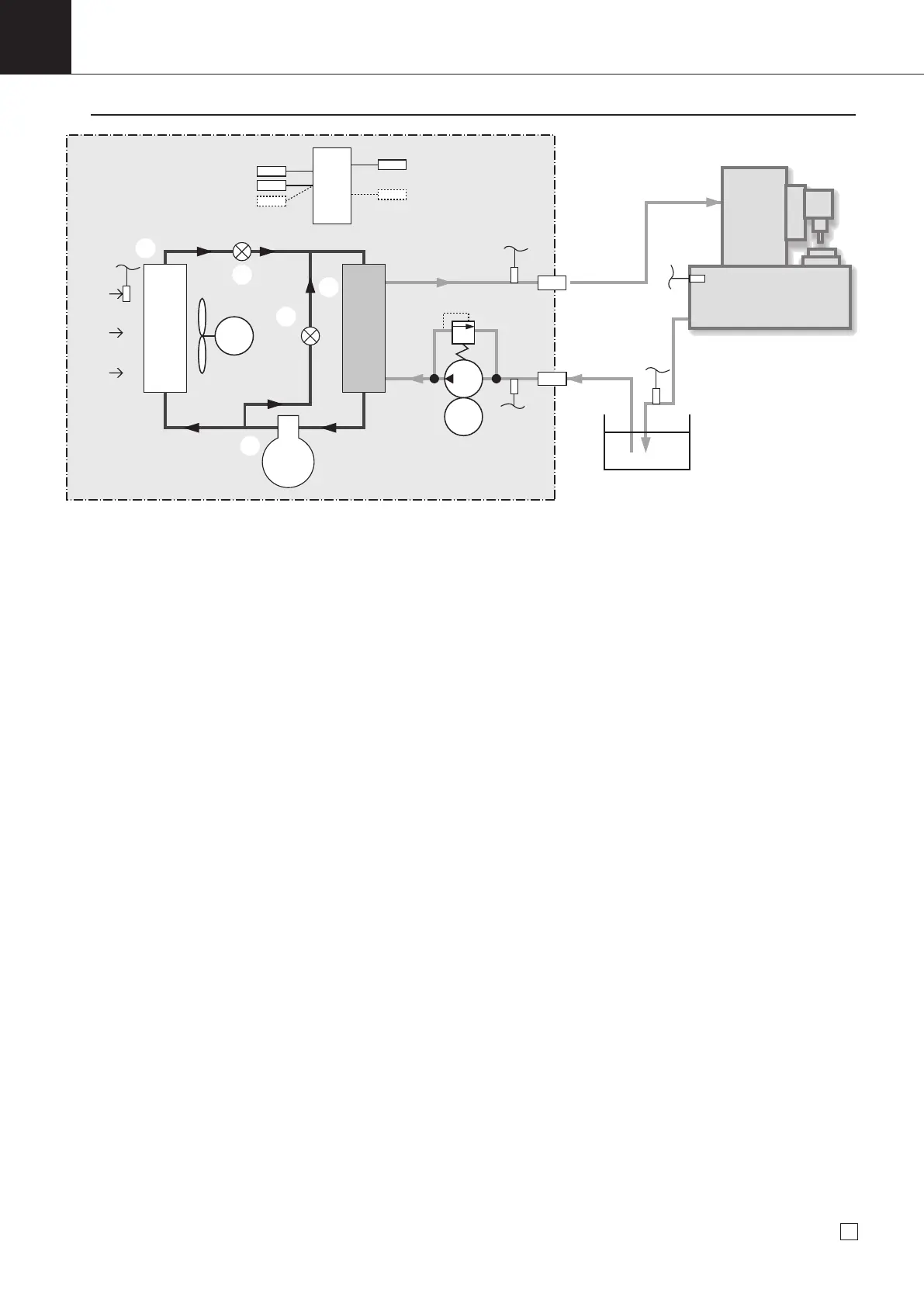
Principle of Oil Cooling Unit
1
M
M
Pressure reducing mechanism
B
Fan
Bypass
mechanism
Air intake
(Compressor)
Refrigerant
*4
C
D
E
A
Oil pump
Relief valve
Oil inlet
Oil outlet
Tank
Machine tool
Condenser
Evaporator (Cooler)
Control board
*2
*5
*3
(Oil)
*1
Inlet oil thermistor (*1)
Outlet oil thermistor (*2)
Returned oil thermistor (*3)
(Optional)
Room thermistor
(*4)
Machine body thermistor
(*5)
(Optional)
[Description of Refrigeration Cycle]
A : Through the compressor, the refrigerant gas turns to be high-temperature and high-pressure compressed gas for
facility cooling and liquefaction with the condenser.
B : The high-temperature and high-pressure gas produced through the compressor is cooled and condensed through
the condenser with air to convert the gas into high-temperature and high-pressure liquid.
C : At
the pressure reducing mechanism, this high-temperature and high-pressure liquid is throttled and decompresses to
convert into low-temperature and low-pressure liquid for facilitating evaporation with the cooler.
D : Through the cooler, the low-temperature and low-pressure gas produced through the pressure reducing mechanism
draws heat from oil evaporation (cool the oil) and turns to low-temperature and low-pressure gas.
E : The bypass mechanism allows control of the cooling capacity under a low load condition by adjustment of hot and
high-pressure gas volume supplied to the cooler.
The Oil Cooling Unit is using a refrigeration cycle shown in Figure above same as Air conditioners, just different
cooling object. Consequently, knowledge required for basic services is the same as that for air conditioners but
different in some points particularly from the air conditioners. The following section describes these different points.
1. Functions of EEV (for main circuit) and MOV (for hot gas)
The electronic expansion valve for main circuit and the motor operated valve for hot gas are used for capacity
control at the minimum compressor operating frequency or less. Required to adjust as follows.
Setting: The fully closed point of electronic expansion valve for main circuit and motor operated valve for hot gas [fully closed pulse of
EEV for main circuit] and [fully closed pulse of motor operated valve for hot gas] should be set on the control board by each unit.
(When replacing the EEV for main circuit, motor operated valve for hot gas or control board, pay close attention.)
2. Oil Pump
Since the Oil Cooling Unit is subject to cooling of oil, oil pump is equipped instead of a fan on the Air-Con indoor
side. The following section describes the features of the oil pump.
① When the external resistance pressure reaches 0.5 MPa or more, (AKZ14A), 0.6 MPa or more (AKZ32A,
43A, 56A, 90A), the relief valve will be activated.
② Since the external resistance point (field piping) is an item to be designed by users, check carefully.
3. Characteristics of Electrical System
Basically, the electrical system is the same as that of air conditioners but has the following characteristics.
① The Oil Cooling Unit has nothing equivalent to the operation switch. Be noted that the Oil Cooling Unit starts
running as soon as the power supply turns ON. Normally, the Oil Cooling Unit exchanges signals with a
machine controller, and runs under ON-OFF signal from the machine tool side.
② The Oil Cooling Unit has an enhanced readout function of internal operation data. Refer to information in "
7
Troubleshooting" to conduct servicing.
00_PB00540A_M10.indb 8 2023/08/09 12:58:50