82
7
Troubleshooting
Troubleshooting According to Alarm Code
3
Using the control panel to put the system into
“
service monitor mode
”
will make it possible to check the history of
alarm codes and data when an alarm or warning occurs.
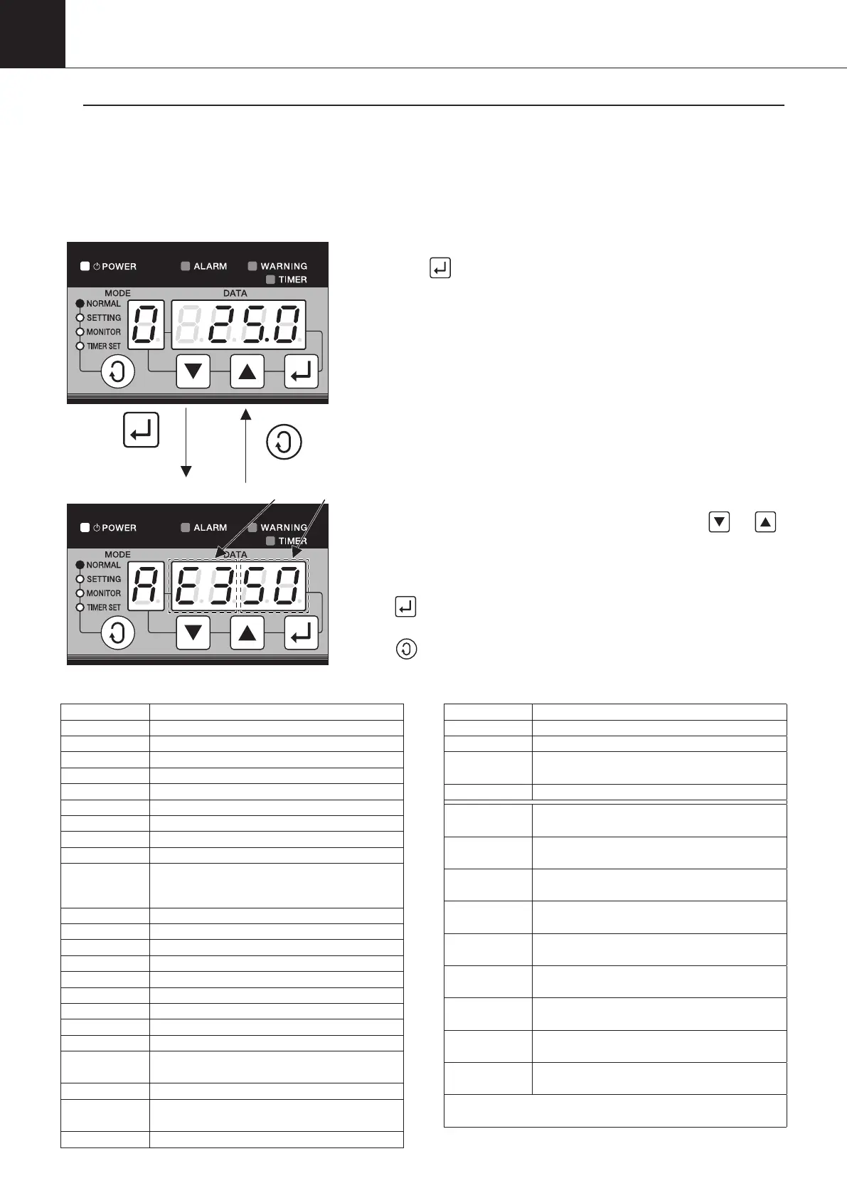
3-1. Control Panel Operation Procedure
While in normal mode (with the NORMAL lamp ON), press and
hold the
button for a period of five seconds, the MONITOR
lamp will start flashing to shift to service monitor mode.
When alarm codes and their detailed data are displayed,
“
A
”
is
displayed in the
“
MODE
”
section,
“
E
”
is displayed while warning
codes and their detailed data are displayed.
As for alarm code, the left 2 digits of the DATA section represent a
code and the right 2 digits represent the classification.
The current data number can be changed with the
“
”
“
”
buttons.
The desired data number is displayed in the data display section
for about 0.5 seconds, and then, data will be displayed.
If
“
”
button is pressed, detailed data is skipped, and alarm
code or warning code of the last one is displayed.
If
“
”
button is pressed in the service monitor mode, the
operation mode returns to the normal one.
Press and hold
for five seconds
Code
<Service monitor mode (Alarm) >
<Normal mode>
Display item of Service monitor mode (Alarm)
Data No. Item
n0.00 Alarm code 0 (latest)
n0.01
Machine temperature (when an alarm occurs)
n0.02
Outlet oil temperature (when an alarm occurs)
n0.03
Room temperature (when an alarm occurs)
n0.04
Inlet oil temperature (when an alarm occurs)
n0.05
Spare, suction pipe temperature (when an alarm occurs)
n0.06
Discharge pipe temperature (when an alarm occurs)
n0.07
Condenser temperature (when an alarm occurs)
n0.08
EE valve outlet temperature (when an alarm occurs)
n0.09
IPM temperature (AKZ14A–43A-500 when an alarm occurs)
Radiator fin temperature (AKZ90A, AKZ56A-500,
AKZ90A-500 when an alarm occurs)
n0.10
Electric component box inside temperature (when an alarm occurs)
n0.11
Compressor command revolutions (when an alarm occurs)
n0.12 EE valve opening (when an alarm occurs)
n0.13 MO valve opening (when an alarm occurs)
n0.14 DC fan rpm (when an alarm occurs)
n0.15 DC voltage (when an alarm occurs)
n0.16 DC current value (when an alarm occurs)
n0.17 Alarm occurrence frequency (total)
n0.18 Power supply frequency (total)
n0.19
Cumulative time (total) of compressor running to
alarm occurrence in hour and minute (in 24 hours)
n0.20 Same as the above, day (32767 max.)
n0.21
Cumulative time (total) of pump running to alarm
occurrence in hour and minute (in 24 hours)
n0.22 Same as the above, day (32767 max.)
Data No. Item
n0.23
Cumulative power supply time (total) hour, minute (in 24 hours)
n0.24 Same as the above, days (32767 max.)
n0.25
Power supply time from power on to alarm
occurrence, minute, second
n0.26 Same as the above, hour (32767 max.)
n1.00
Alarm code 1 (last time)
…Detailed data (26 data) to n1.26
n2.00
Alarm code 2 (last but one)
…Detailed data (26 data) to n2.26
n3.00
Alarm code 3 (last but two)
…Detailed data (26 data) to n3.26
n4.00
Alarm code 4 (last but three)
…Detailed data (26 data) to n4.26
n5.00
Alarm code 5 (last but four)
…Detailed data (26 data) to n5.26
n6.00
Alarm code 6 (last but five)
…Detailed data (26 data) to n6.26
n7.00
Alarm code 7 (last but six)
…Detailed data (26 data) to n7.26
n8.00
Alarm code 8 (last but seven)
…Detailed data (26 data) to n8.26
n9.00
Alarm code 9 (last but eight)
…Detailed data (26 data) to n9.26
… Maximally, ten alarm codes and their detailed data (26
data) are stored as history.
Though alarm and warning that occur within a minute after power is
supplied are displayed on the control panel, they are not stored as history.
00_PB00540A_M10.indb 82 2023/08/09 12:59:05