114
7
Troubleshooting
5
Troubleshooting
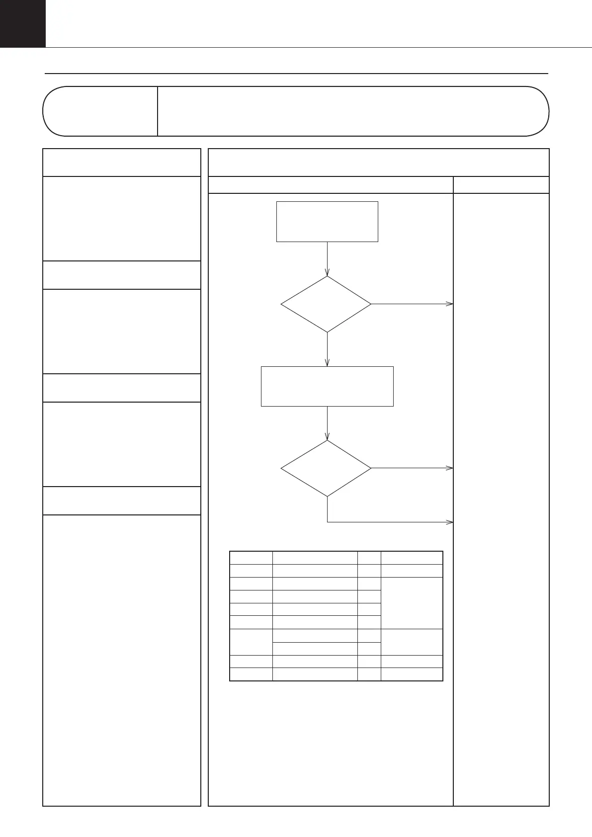
Diagnosis Countermeasures
1
Applicable Models
AKZ**A (All series)
2
Methods of Malfunction Detection
Detect by the resistance
detected by the thermistor.
3
Malfunction Decision Conditions
The thermistor disconnection or
short-circuit is detected.
4
Supposed Causes
1Faulty thermistor
1Faulty control board (A1P)
1Faulty thermistor connection
Control panel display
H1,J3,J4,
J6,JH,JJ,P3,P4
Malfunction of Thermistors
Connect properly.
NO
Normal
(*1)
YES
Replace the thermistor.
Replace the control
board (A1P).
(See page 122/137)
NO
Normal
YES
Check the connection
of connector.
Remove the thermistor from the
control board, and measure the
resistance with a tester.
"Check 1" (See page 116)
*1: Warning codes and applicable thermistors
(a) The warning code represents “control panel display
(service monitor history display)”.
(b) If it is not used as control, the warning code will not be
displayed.
Applicable thermistor
Room thermistor (b)
Discharge thermistor
EE valve outlet thermistor
Condenser thermistor
Inlet oil thermistor (b)
Outlet oil thermistor (b)
Optional thermistor
Switch box thermistor
Radiation fin thermistor
Symbol
Th-3
Th-6
Th-8
Th-7
Th-4
Th-2
Th-9
Th-300
Th-Fin
Connector No.
CN10
S9
CN11
-
CN18
Warning code (a)
H1 (H1)
J3 (J3)
J4 (J4)
J6 (J6)
JH (JH)
- (JJ)
- (P3)
P4 (P4)
00_PB00540A_M10.indb 114 2023/08/09 12:59:08