126
8
Disassembling Procedure
Work Procedure Point
WARNING
Before disassembling work, be sure
to turn OFF all power supplies.
1
Remove the switch box cover in
accordance with “Procedure for
Removing Outside Panel Block
(P.118)”.
1
Remove the control panel mounting
plate in accordance with “Procedure
for Removing Switch Box (P.121)”.
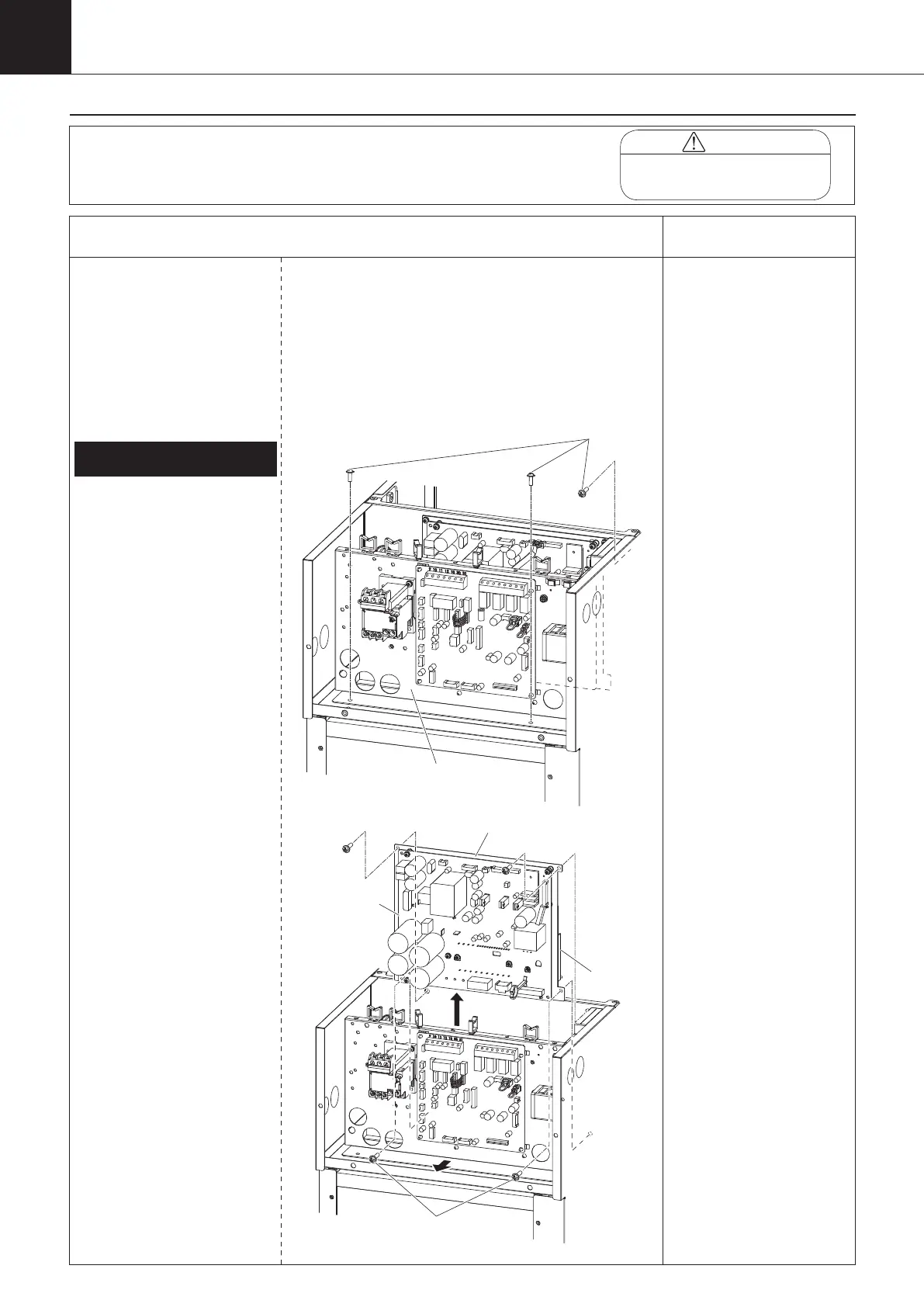
Procedure for Removing Inverter
Board (AKZ14A–43A-500)
① Unscrew the three screws
fixing the intermediate
panel.
②
Disconnect all the wiring connected to
the inverter board (A2P).
1)
Compressor (relay connector in
switch box)
2)
DC fan motor (CN15)
3)
Control board signal wire 1 (CN6)
4)
Control board signal wire 2
(CN110)
5)
Noise filter board signal wire 1
(CN650)
6)
Noise filter board signal wire 2
(CN103)
7)
Main circuit power supply wire
(R1: F504, S1: F505, T1: F506)*
8)
Reactor (DCL1, DCL2)
*Connector is located
on the noise filter
board (A3P) side.
③ Slide the intermediate
panel forward.
④ When removing the
inverter board (A2P),
unscrew the four screws
on the inverter board
mounting plate, and
remove the inverter board
with heat sink attached
to the inverter board
mounting plate. (*1)
1.
Removing inverter board (A2P)
*1
When replacing the inverter
board, handle it as the
“inverter board assembly”,
i.e., inverter board integrated
with heat sink.
Never replace the inverter
board only. Replacement of
the inverter board only may
cause degradation of the
radiation performance of the
heat sink, leading to smoke
or ignition.
Intermediate panel
(A2P)
Inverter board mounting plate
Heat sink
Four screws
00_PB00540A_M10.indb 126 2023/08/09 12:59:14