●Disassembling Procedure
137
8
Disassembling Procedure
Disassembling
Procedure
Work Procedure Point
WARNING
Before disassembling work, be sure
to turn OFF all power supplies.
1
Remove the switch box cover in
accordance with “Procedure for
Removing Outside Panel Block
(P.133)”.
1
Remove the control panel mounting
plate in accordance with “Procedure
for Removing Switch Box (P.136)”.
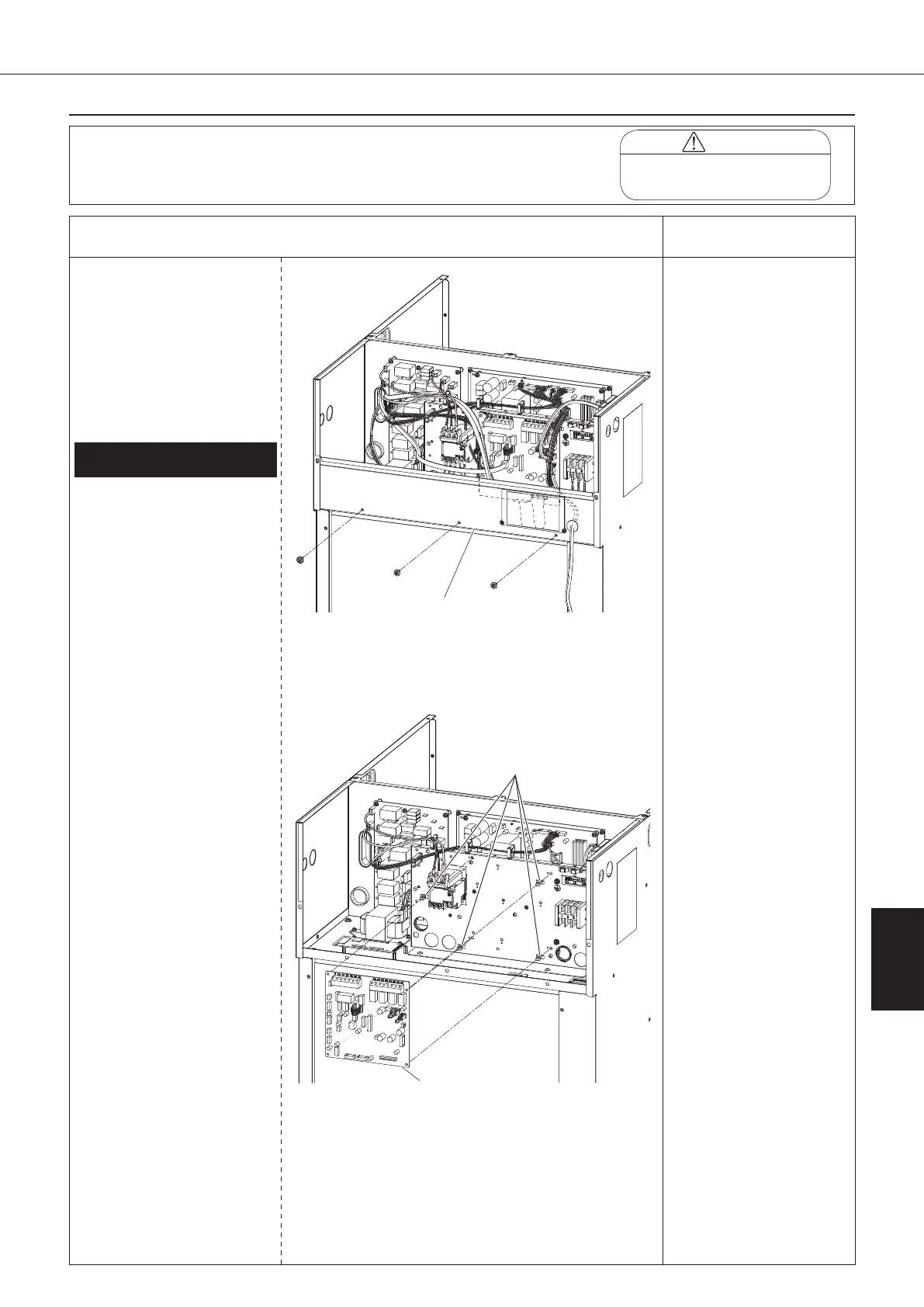
Procedure for Removing Control
Board
*1
1.
Removing control board (A1P)
① Disconnect all the wiring
connected on the control
board (A1P).
1) Thermistor assembly
(S9)
2) Outlet oil temperature
thermistor (CN11)
3) EE valve coil (S90)
4) MO valve coil (CN7)
5) High pressure switch
(S171)*2
6) Compressor protective
thermostat (S172)
7) Signal terminal block
(X2M)*3
8) Inverter board power
supply wire (S200)
9) Inverter board signal
wire 1 (S170)
10) Inverter board signal
wire 2 (S140)
11) Inverter board signal
wire 3 (S60)
12) Over current relay
signal wire (S182)
13) Optional board signal
wire*3
*2: "-C" models only
*3: connected units
only
② Remove the four locking
card spacers to take off
the control board (A1P).
*1
When replacing the control
board (A1P), change the
setting data referring to the
“Replacing Control Board”
(P.149).
Control panel
mounting plate
Locking card
spacer
Control board
00_PB00540A_M10.indb 137 2023/08/09 12:59:20