74
PIM00504
[Safety Valve Adjustment Instructions]
1) Referring to the enlarged view of the safety valve on the next page, loosen the lock nut. (Lock
nut: M10, width across flats of 14 mm)
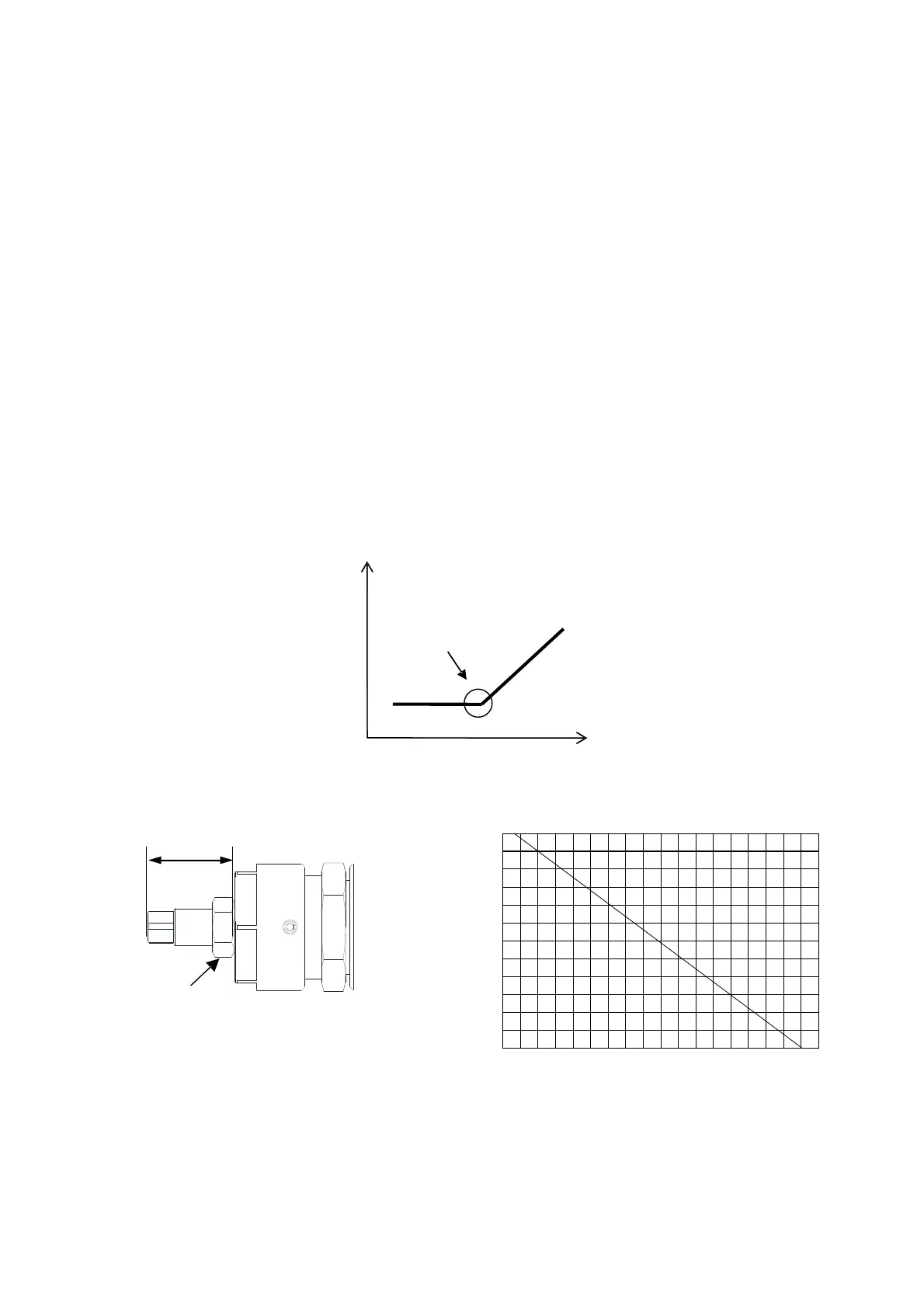
2) In accordance with the guidance diagram for the length of the pressure adjusting screw, bring
the screw to about the length corresponding to the desired control pressure. (The tip of the
adjusting screw has four faces, with width across flats of 7 mm.)
3) Turn on the power to the hydraulic unit, establish the setting mode by panel key operation, and
adjust the pressure setting to the desired pressure.
4) Select [n05] (motor rotation speed indication) in the monitor mode by panel key operation to
display the current motor rotation speed.
5) Adjust the pressure adjusting screw length in the longitudinal direction and find the actuation
start point shown in the figure below.
6) Turn the pressure adjusting screw clockwise three fourths of a turn from the actuation start point.
7) Tighten the lock nut to complete the adjustment. (When tightening the lock nut, take care that
the adjusting screw does not turn.)
7.0
6.5
6.0
5.5
5.0
4.5
4.0
3.5
3.0
2.5
2.0
1.5
1.0
15
19
17
16
18 20
21
22 23 24
Pressure adjustment screw length
Guidance diagram
Lock nut
Pressure adjustment screw length (mm)
PC set pressure (MPa)
<Detail of Safety Valve>
Pressure adjustment screw length
Current rotational speed
ctuation start point