77
PIM00504
Chapter 14. Output Signal Timing Charts
The start/stop signals (digital input 0) in the timing charts all assume that the value set for [P00: Start/stop
signal switching] is “1” (default value).
When the value set for [P00: Start/stop signal switching] is “0”, the ON and OFF statuses of the start/stop
signal (digital input 0) are inverted.
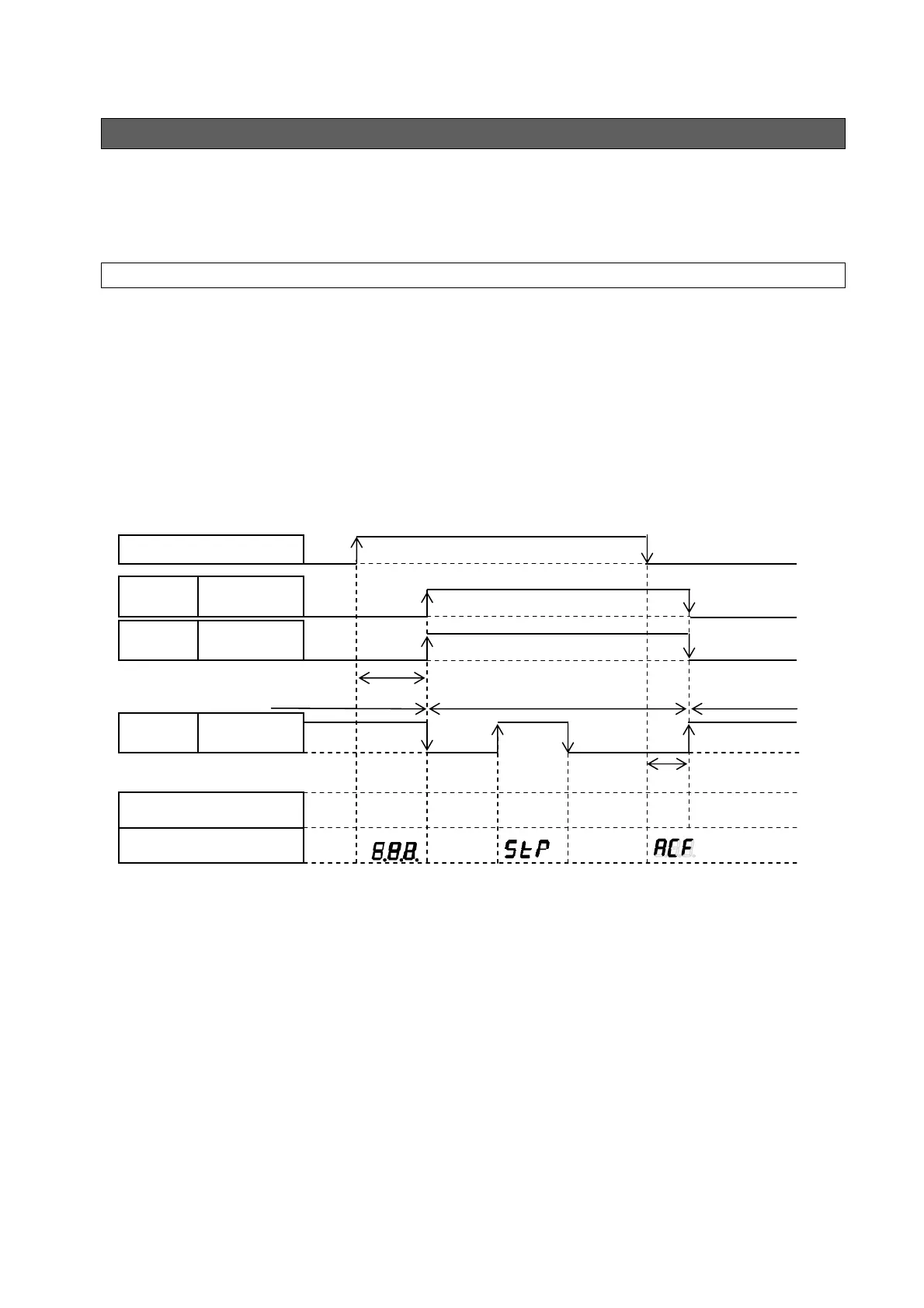
14.1 Timing Chart at Powering Up
The timing chart at powering up differs depending on the type of power supply as shown below.
When sharing control power supply:
• Judge the charging completed/not completed status based on the alarm output or DOUT (READY
output).
• An alarm output before charging or after stopping indicates an abnormal status.
Common power supply source to control and main circuit
Command
ossible
OFF
Waiting
to run
Charging
ON
OFF
Max. 3 seconds
ON
Command not possible
Power suppl
, 3-phase,
Digital
input
DIN1
(start/stop signal)
Digital
output
DOUT
(READY output)
OFF
Approx. 20 msec
Contact
output
ALM_a
Unit operation
Display
Normal
running
Actual
pressure
Command
impossible
Actual
pressure
Normal
running
OFF ON OFF
ON
OFF
Stop