34
PIM00504
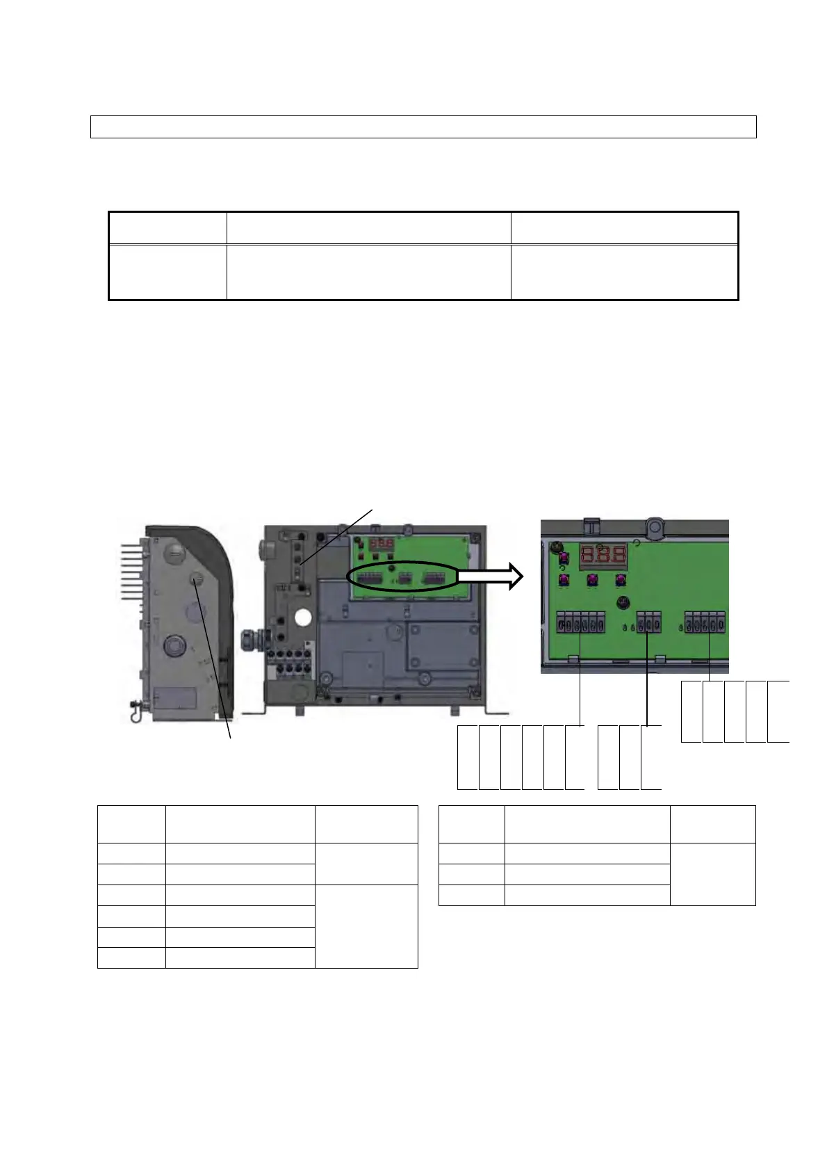
9.5 Connection of Input/Output Signal Cables
1) Prepare cables and cable clamps. For the cables, use shielded cabtyre cables, and be sure to
complete terminal processing of the shielding wire.
<<Recommended Items>>
Cable Size Recommended Cable Recommended Cable Clamp
0.3 - 0.5 mm
2
(AWG20 - 22)
KVC-36SB 0.3 – 0.5 mm
2
(KURAMO ELECTRIC)
OA-W15-07 (OHM ELECTRIC)
Applicable cable outer diameter:
φ5 – φ7
2) Connect the cables through the controller’s cable port. At the cable port, use a cable clamp
appropriate to ensure the port satisfies protection class IP54 or better.
3) Check the specifications of each signal cable, and connect them to the I/O signal terminal block. If
measures against loose strands or corrosion at the end of the cable are required, use rod-type crimp
terminals with insulating cladding. (Recommended crimp terminal: 216 – 322 (0.3 mm
2
), 216 – 221
(0.5 mm
2
), WAGO)
4) You are recommended to ground at one side. When grounding inside the controller, crimp a ring-type
crimp terminal with insulating cladding onto the end of the cable with a dedicated tool, and connect it
with a control/signal cable grounding screw (M4).
Terminal
code
Signal name Remarks
Terminal
code
Signal name Remarks
COM1 Digital output common
See 9.5.2
Digital outputs.
ALMa Alarm output, NO contact
See 9.5.3
Contact
outputs.
DOUT Digital outputs ALMb Alarm output, NC contact
DIN0 Digital input 0
See 9.5.1
Digital inputs.
COM Alarm output common
DIN1 Digital input 1
DIN2 Digital input 2
COM2 Digital input common
Signal cable port
φ16 hole
* When RS422/485
communications option
selected
Ground terminal
COM1
DOUT
DIN0
DIN1
DIN2
COM2
ALMa
ALMb
COM
DGND
RXD−
RXD+
TXD−
TXD+