31
PIM00504
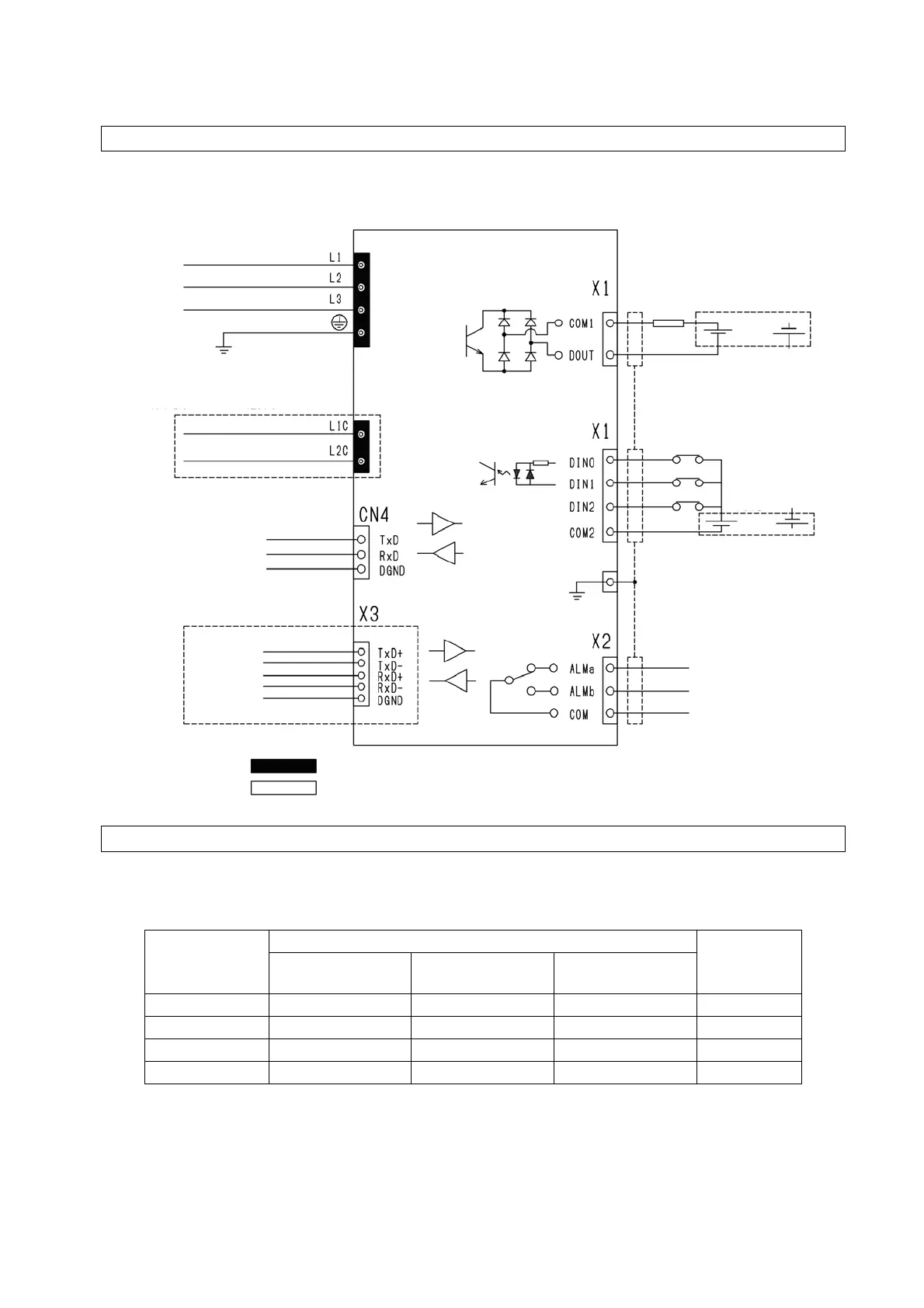
9.2 Overall Wiring Diagram
9.3 Installation of the Breaker
In order to prevent power-supply-related accidents, be sure to use a no-fuse breaker conforming to
EN60947-2 in the power supply connection line. The rated capacity of the breaker should be as indicated
in the table below. There are no inrush currents with ECORICH.
Product Model
Power Supply Voltage and Frequency
Breaker
Setting
3-phase
200 V 50 Hz
3-phase
200 V 60 Hz
3-phase
220 V 60 Hz
EHU1404-40 6.0 A 5.9 A 5.5 A 15 A
EHU2504-40 7.0 A 7.0 A 6.7 A 15 A
EHU2507-40 4.7 A 4.5 A 4.3 A 15 A
EHU3007-40 10.3 A 10.3 A 9.7 A 15 A
Input power supply
3-phase 200/200/220 V, 50/60/60 Hz
Control power supply input
1-phase 200/200/220 V, 50/60/60 Hz
∗ Only when control power supply option
selected
Communications port for maintenance
(Hybrid-Win connection point)
RS422/RS485
communications
* Only when communications
option selected
Power supply
line ground
Digital output
or
Ready to run
Positive common
Negative common
External power supply (DC+24 V)
Max. current 50 mA
Digital input
Start/stop signal
(Not used)
(Not used)
or
Positive common
Negative common
External power supply (DC+24 V)
Input current 5 mA
(when DC24 V applied)
Control/communications line ground
Switching capacity 10 mA to 1 A
(DC30 V max.)
Located on the controller’s main power supply terminal block
Located on the controller’s signal line terminal block
larm contact output