Si33-105 Operation Flowcharts
Troubleshooting R407C PLUS Series Heat Recovery System 139
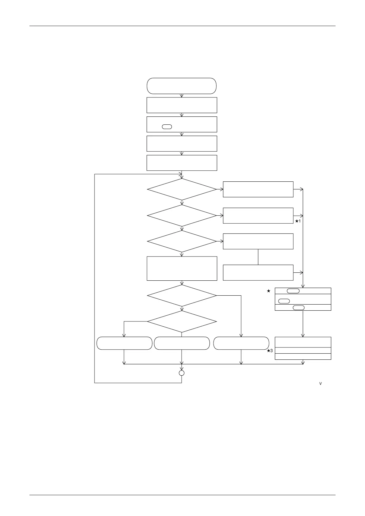
1. Operation Flowcharts
1.1 Indoor Unit Operation Flowchart
Start
Power on
Louver lock detection
Remote contoller lamp on
Operation ON/OFF?
Action of safety device?
Fan or Temperature control?
Cooling or heating?
Cooling operation Heating operation Fan operation
Is operation display
lamp blinking?
Initialize electronic expansion
valve YIE
Operation display lamp: OFF
Operation display: Blinking
Malfunction code: Displayed
Operation display: Off
Malfunction mode Display:
Cancelled
Fan M1F :OFF
Louver M1S :OFF
Drain-up kit (M1P): OFF
Humidifier (Hu) : OFF
Electronic expansion valve
Y1E Closed
Optional auxiliary electric
heater (K1R): OFF
Depress reset Operation ON/OFF
switch
Operation display lamp: ON
Air flow rate setting display: ON
Air flow direction setting display:
ON
Temperature setting display: ON
Indicates previous settings for air flow
rate and direction and temperature
NO
ON
OFF
YES
NO
(Option)
YES
Fan
(Ventilation)
Temperature
contorl
Heating
A
H
1
H
2
H
3
(VF021)
"
1 In the event of a malfunction, the malfunction code is displayed in the remote controller’s
malfunction code display.
"
2 When the auxiliary electric heater is on, the fan stops after one minute residual operation.
"
3 When the drain-up kit is ON, it stops after five minutes residual operation.