Si33-105 Refrigerant System Diagram
Function R407C PLUS Series Heat Recovery System 37
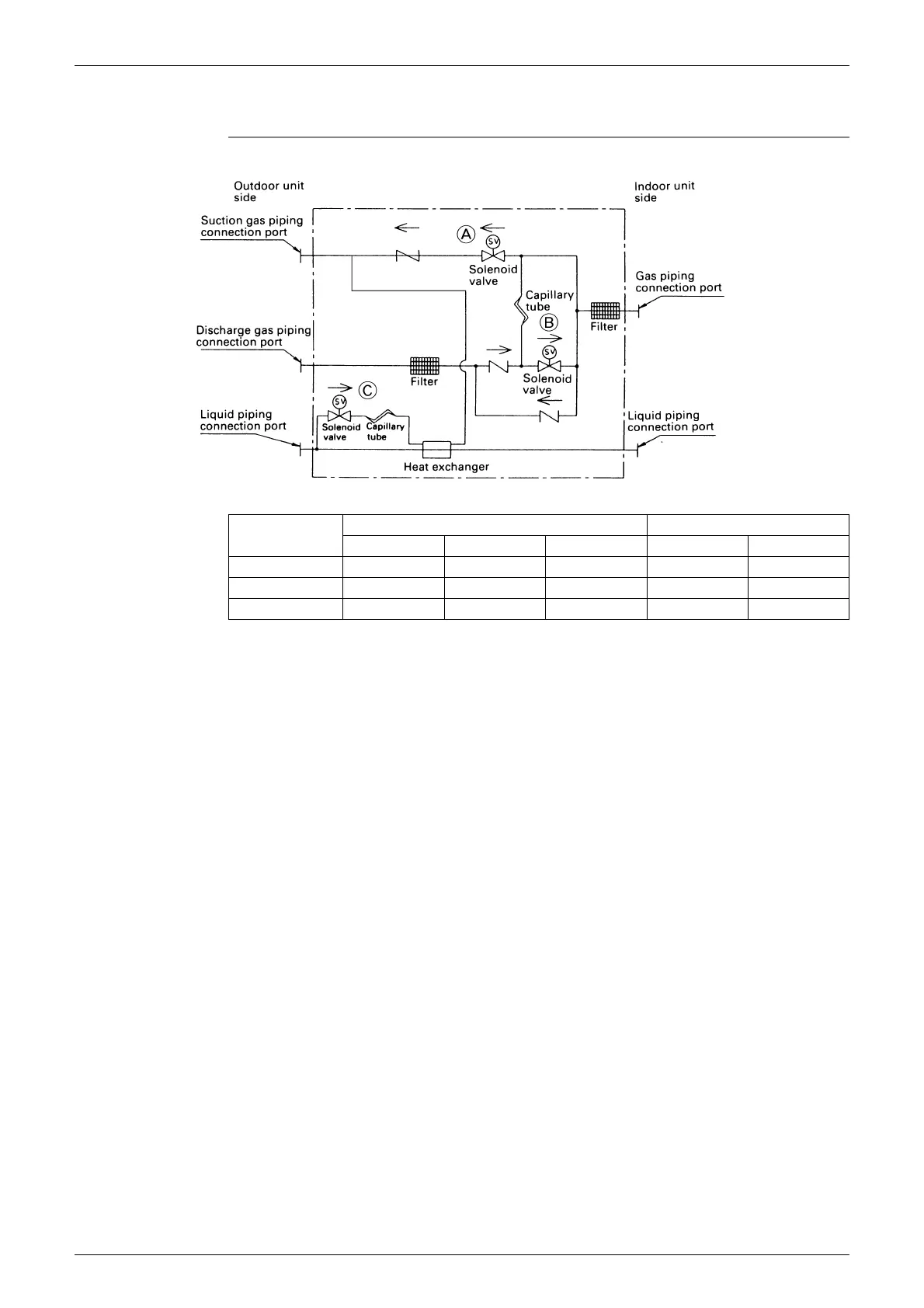
1.2 BS unit Refrigerant System Diagram
BSVP100KJV1
A.Solenoid valve (suction side) Y2S
Turns ON during normal cooling operation. (Connects indoor unit gas pipe and outdoor unit
suction pipe)
B.Solenoid valve (discharge side) Y3S
Turns ON when the indoor unit is set to the heating mode. (Connects indoor unit gas pipe and
outdoor unit discharge pipe)
C.Solenoid valve (for drift-prevention injection) Y1S
Turns ON only the BS unit of the indoor unit in heating operation when the system is used for
simultaneous cooling/heating operations.
∗
Do not replace the valve body
Model
Outdoor unit Indoor unit
Liquid Suction gas Discharge gas Liquid Gas
BSVP100KJV1
C
9.5
C
15.9
C
12.7
C
9.5
C
15.9
BSVP160KJV1
C
9.5
C
19.1
C
15.9
C
9.5
C
19.1
BSVP250KJV1
C
12.7
C
25.4
C
19.1
C
12.7
C
25.4