SiUS12-928_B Check
Service Diagnosis 192
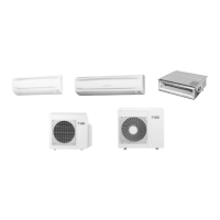
7.2 Fan Motor Connector Check
Check No.02 CTXS/FTXS Series
1. Check the connection of connector.
2. Check motor power supply voltage output (pins 4 - 7).
3. Check motor control voltage (pins 4 - 3).
4. Check rotation command voltage output (pins 4 - 2).
5. Check rotation pulse input (pins 4 - 1).
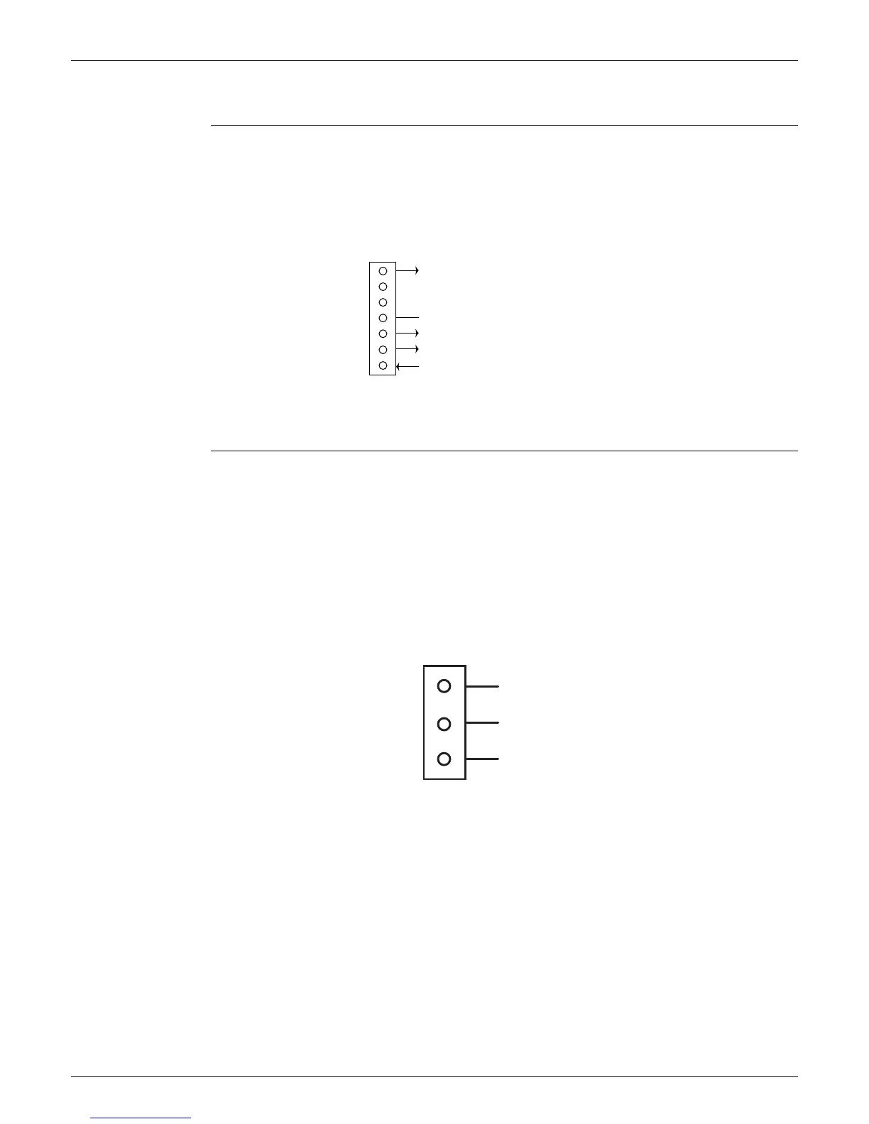
7.3 Hall IC Check
Check No.04 CDXS/FDXS Series
1. Check the connector connection.
2. With the power on, operation off, and the connector connected, check the following.
Output voltage of about 5 V between pins 1 and 3.
Generation of 3 pulses between pins 2 and 3 when the fan motor is operating.
If NG in step 1 Defective PCB Replace the PCB.
If NG in step 2 Defective Hall IC Replace the fan motor.
If OK in both steps 1 and 2 Replace the PCB.
7
6
5
4
3
2
1
S1
(R12404)
Motor power supply voltage (310 ~ 340 VDC)
Unused
Unused
GND
Motor control voltage (15 VDC)
Rotation command voltage (1~ 5 VDC)
Rotation pulse input
 Loading...
