EasyManuals Logo

Daikin SUPER MULTI NX G Series Service Manual

Daikin SUPER MULTI NX G Series
285 pages
To Next Page IconTo Next Page
To Previous Page IconTo Previous Page
Page #212 background imageLoading...
Page #212 background image
SiUS12-928_B Outdoor Unit: 2MXS18GVJU
Removal Procedure 204
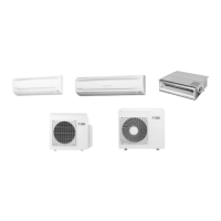
1.2 Removal of Electrical Box
Procedure Warning Be sure to wait for 10 minutes or more after turning off all power supplies
before disassembling work.
Step
Procedure Points
1. Disconnect the connecting
wires.
The US model has a
protection plate on the right
side panel.
Remove the 2 screws to
remove the protection plate.
1
Remove the terminal
board fixing screw.
The wires are fixed to the
terminal board with screws.
2
Remove all the screws of
the connecting wires and
the power supply wires.
3
Remove the screw of the
ground wire.
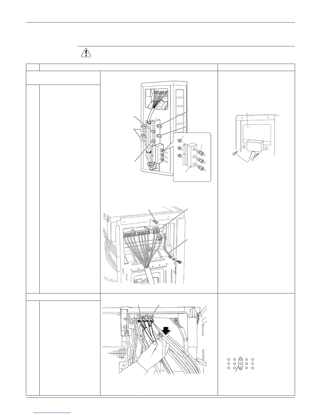
2. Disconnect the harnesses.
[S20]: White
[S21]: Red
Bundle the harnesses of the
electronic expansion valve
coil with clamp.
Pull out the clamp.
When reassembling, insert
the clamp into one of the
holes.
1
Disconnect the 2
connectors for the
electronic expansion
valve coil [S20] [S21].
Liquid (room A)
Liquid (room B)
Gas (room A)
Gas (room B)
(R17343)
Electronic expansion
valve coil
Conduit
Lock nut
Conduit
mounting plate
Screw
(R17395)
Protection plate
RoomA
RoomB
Terminal board fixing screw
Power supply
Ground wire
(R17344)
[S20] [S21]
(R17400)
For the electronic
expansion valve coil
(R17396)

Table of Contents

Other manuals for Daikin SUPER MULTI NX G Series

Questions and Answers:

Question and Answer IconNeed help?

Do you have a question about the Daikin SUPER MULTI NX G Series and is the answer not in the manual?

Daikin SUPER MULTI NX G Series Specifications

General IconGeneral
BrandDaikin
ModelSUPER MULTI NX G Series
CategoryAir Conditioner
LanguageEnglish

Related product manuals