EasyManuals Logo

Daikin SUPER MULTI NX G Series Service Manual

Daikin SUPER MULTI NX G Series
285 pages
To Next Page IconTo Next Page
To Previous Page IconTo Previous Page
Page #217 background imageLoading...
Page #217 background image
Outdoor Unit: 2MXS18GVJU SiUS12-928_B
209 Removal Procedure
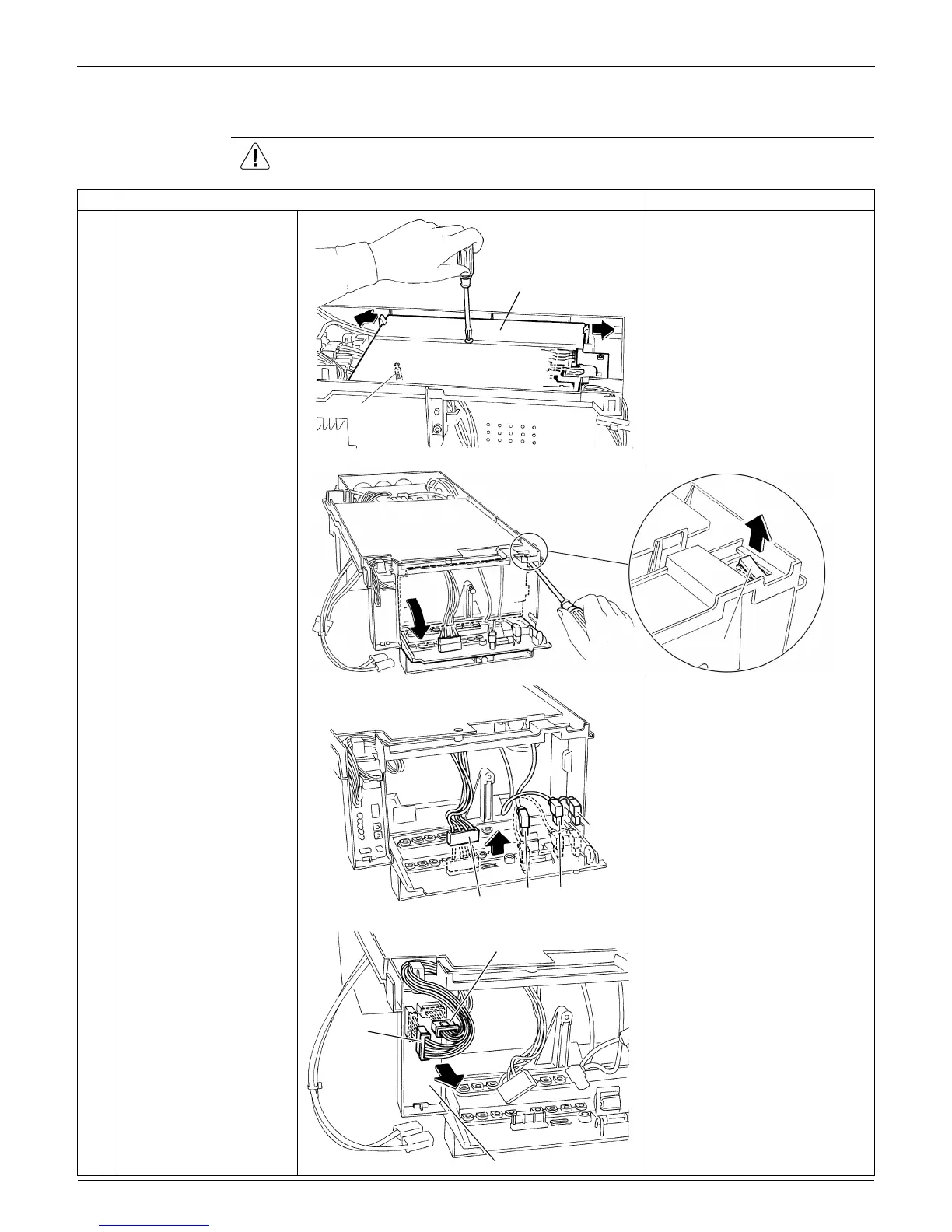
1.3 Removal of PCBs
Procedure Warning Be sure to wait for 10 minutes or more after turning off all power supplies
before disassembling work.
Step
Procedure Points
1
Remove the screw of the
main PCB, and unfasten
the 2 hooks.
When reassembling, insert
the base bar into the hole of
the main PCB.
2
Unfasten the hook of the
terminal board, and open
the terminal board.
3
Disconnect each
connector [S11] [HE] [HL]
[HN] on the back of the
terminal board.
4
Disconnect the
connectors [S52] [S102]
from the service monitor
PCB.
Main PCB
(R2177)
Base bar
(R2178)
Hook
[S11]
[HL] [HN]
(R17403)
[HE]
(R17347)
[S102]
[S52]
Service monitor PCB

Table of Contents

Other manuals for Daikin SUPER MULTI NX G Series

Questions and Answers:

Question and Answer IconNeed help?

Do you have a question about the Daikin SUPER MULTI NX G Series and is the answer not in the manual?

Daikin SUPER MULTI NX G Series Specifications

General IconGeneral
BrandDaikin
ModelSUPER MULTI NX G Series
CategoryAir Conditioner
LanguageEnglish

Related product manuals