Home
Daikin
Air Conditioner
SUPER MULTI NX G Series
Daikin SUPER MULTI NX G Series Service Manual
4
of 1
of 1 rating
285 pages
Give review
Manual
Specs
To Next Page
To Next Page
To Previous Page
To Previous Page
Loading...
SiUS12-928_B
Outdoor Unit
Printed Circuit Board Connector Wiring Di
agram
30
MID2 (Inverter PCB)
SPM
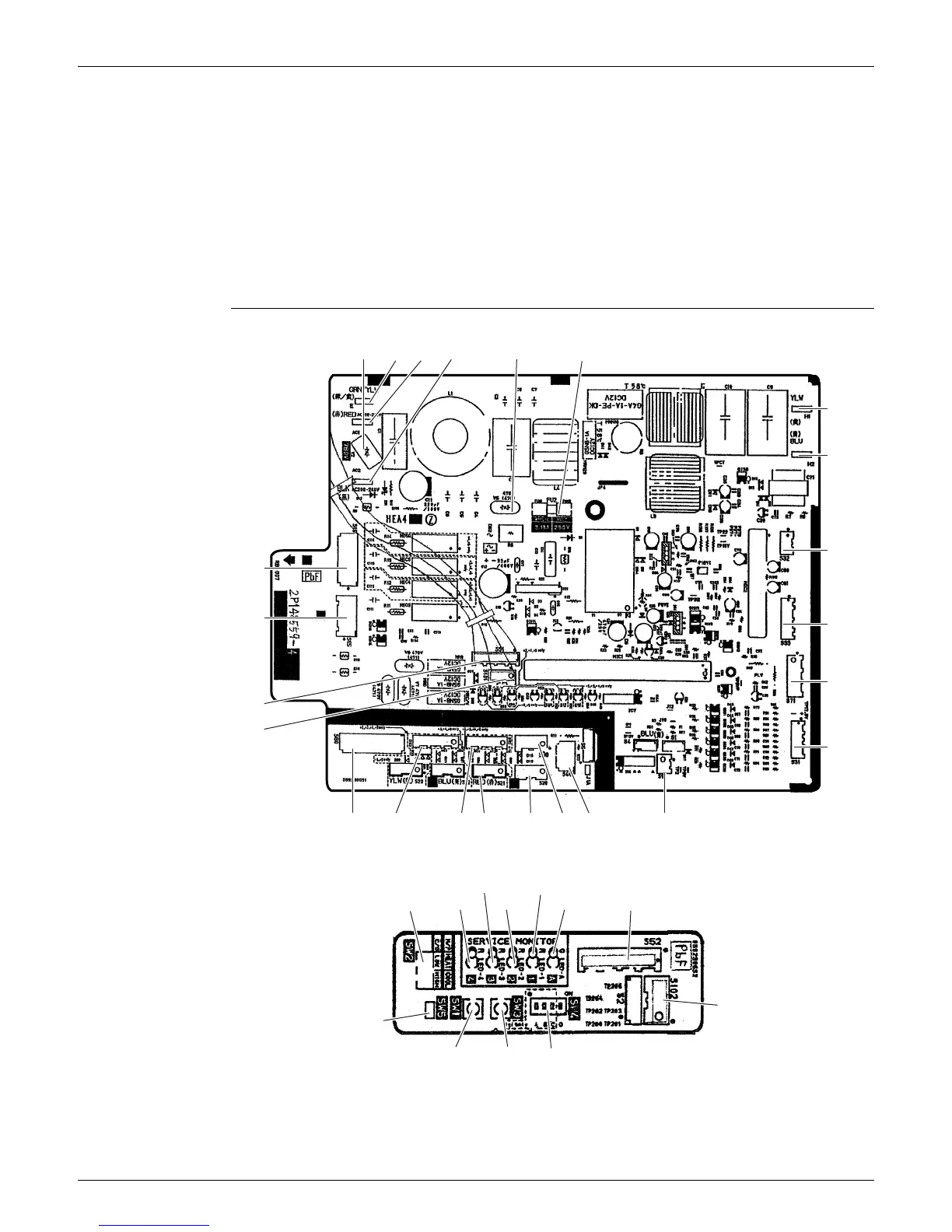
PCB Detail
Main PCB
Service Monitor PCB
1)
S34, S72
C
onnector for main PCB
2)
S70
C
onnector for outdoor fan motor
3)
FU201
Fuse (3.15 A, 250 V)
4)
W, V, U, N
Connector for compressor
1)
CN11, CN14
C
onnector for main PCB
2)
L1, L
2
Connector for reactor
S10
S15
S51
S101
S80
S93
S92
S21
S20
S90
S40
S91
S31
S71
S33
S32
H1
(yellow)
(blue)
H2
V2
E
AC1
AC2
V5
FU2
2P148559-3
SW2
SW5
SW1
SW3
SW4
2P148559-3
LED4
LED2
LED A
S102
S52
LED3
LED1
37
39
Table of Contents
Default Chapter
2
Table of Contents
2
Safety Considerations
7
Safety Considerations for Repair
7
Safety Considerations for Users
8
Part 1
9
Part
9
List of Functions
9
Functions
10
Part 2
15
Specifications
15
Indoor Unit
16
Outdoor Unit
21
Part 3
24
Part
24
Indoor Unit
25
Ctxs07Jvju, Ctxs09/12Hvju, Ftxs15/18Hvju
25
Ctxs07Lvju, Ftxs09/12Lvju
27
Ftxs15/18Lvju
30
Fdxs09/12Dvju
33
Fdxs09/12Lvju, Cdxs15/18Lvju
35
Outdoor Unit
37
2Mxs18Gvju
37
3Mxs24Jvju, 4Mxs32Gvju
40
Printed Circuit Board Connector Wiring Diagram
24
Part 4
42
Function and Control
42
Part
42
Main Functions
43
Temperature Control
43
Frequency Principle
43
Airflow Direction Control (CTXS/FTXS Series)
45
Fan Speed Control for Indoor Unit
47
Program Dry Operation
48
Automatic Operation
49
Thermostat Control
50
NIGHT SET Mode
52
ECONO Operation
53
HOME LEAVE Operation
54
INTELLIGENT EYE Operation (CTXS/FTXS Series)
55
Inverter POWERFUL Operation
56
Other Functions
57
Function of Thermistor
59
Control Specification
62
Mode Hierarchy
62
Frequency Control
63
Controls at Mode Changing / Start-Up
65
Discharge Pipe Temperature Control
66
Input Current Control
67
Freeze-Up Protection Control
67
Heating Peak-Cut Control
68
Outdoor Fan Control
69
Liquid Compression Protection Function
69
Defrost Control
70
Low Hz High Pressure Limit
71
Outdoor Electronic Expansion Valve Control
71
Pressure Equalizing Control
73
Malfunctions
76
Part 5
78
Operation Manual
78
System Configuration
79
CTXS-J, CTXS-H, FTXS-H Series
80
Remote Controller
80
AUTO · DRY · COOL · HEAT · FAN Operation
82
Adjusting the Airflow Direction
84
INTELLIGENT EYE Operation
86
POWERFUL Operation
88
OUTDOOR UNIT QUIET Operation
89
HOME LEAVE Operation
90
TIMER Operation
92
Note for Multi System
94
CTXS-L, FTXS-L Series
96
Remote Controller
96
AUTO · DRY · COOL · HEAT · FAN Operation
98
Operating Conditions
99
Adjusting the Airflow Direction and Rate
100
COMFORT AIRFLOW / INTELLIGENT EYE Operation
103
POWERFUL Operation
105
OUTDOOR UNIT QUIET Operation
106
ECONO Operation
107
OFF TIMER Operation
108
ON TIMER Operation
109
WEEKLY TIMER Operation
110
Note for Multi System
116
Quick Reference
118
FDXS-D Series
119
Remote Controller
119
AUTO · DRY · COOL · HEAT · FAN Operation
120
POWERFUL Operation
122
OUTDOOR UNIT QUIET Operation
123
HOME LEAVE Operation
124
TIMER Operation
126
CDXS-L, FDXS-L Series
128
Remote Controller
128
AUTO · DRY · COOL · HEAT · FAN Operation
130
Adjusting the Airflow Rate
132
POWERFUL Operation
133
OUTDOOR UNIT QUIET Operation
134
ECONO Operation
135
OFF TIMER Operation
136
ON TIMER Operation
137
Note for Multi System
138
Quick Reference
140
Part 6
141
Service Diagnosis
141
Troubleshooting with LED
143
Indoor Unit
143
Outdoor Unit
144
Problem Symptoms and Measures
145
Service Check Function
146
ARC452 Series Remote Controller
146
ARC433 Series Remote Controller
149
Code Indication on Remote Controller
152
Indoor Unit
152
Outdoor Unit
153
Troubleshooting for Indoor Unit
154
Indoor Unit PCB Abnormality
154
Part
155
Freeze-Up Protection Control or Heating Peak-Cut Control
156
Fan Motor or Related Abnormality
158
Thermistor or Related Abnormality (Indoor Unit)
161
Signal Transmission Error (between Indoor Unit and Outdoor Unit)
162
Unspecified Voltage (between Indoor Unit and Outdoor Unit)
163
Troubleshooting for Outdoor Unit
164
Refrigerant Shortage
164
Low-Voltage Detection or Over-Voltage Detection
167
Signal Transmission Error (on Outdoor Unit PCB) (24/32 Class Only)
169
Unspecified Voltage (between Indoor Unit and Outdoor Unit) / Anti-Icing Function in Other Rooms
170
Anti-Icing Function
171
Outdoor Unit PCB Abnormality (24/32 Class Only)
173
OL Activation (Compressor Overload)
174
Compressor Lock
175
DC Fan Lock
176
Input Overcurrent Detection
177
Four-Way Valve Abnormality (18 Class Only)
178
Four Way Valve Abnormality (18 Class Only)
178
Discharge Pipe Temperature Control
180
High Pressure Control in Cooling
181
Compressor Sensor System Abnormality (24/32 Class Only)
182
Position Sensor Abnormality
184
CT or Related Abnormality
187
Thermistor or Related Abnormality (Outdoor Unit)
189
Electrical Box Temperature Rise
191
Radiation Fin Temperature Rise
194
Output Overcurrent Detection
197
Check
199
Thermistor Resistance Check
199
Fan Motor Connector Check
200
Hall IC Check
200
Power Supply Waveform Check
201
Outdoor Electronic Expansion Valve Check
202
Four Way Valve Performance Check
203
Inverter Unit Refrigerant System Check
203
Inverter Checker" Check
204
Rotation Pulse Check on the Outdoor Unit PCB
205
Installation Condition Check
206
Discharge Pressure Check
206
Outdoor Fan System Check
207
Main Circuit Short Check
207
Capacitor Voltage Check
208
Power Module Check
209
Removal Procedure
210
Part
210
Outdoor Unit: 2MXS18GVJU
211
Removal of Outer Panels
211
Removal of Electrical Box
212
Removal of Pcbs
217
Removal of Fan Motor
220
Removal of Sound Blankets
221
Removal of Coils / Thermistors
223
Removal of Four Way Valve / Defrost Solenoid Valve
225
Removal of Distributor
227
Removal of Compressor
228
Outdoor Unit: 3MXS24JVJU, 4MXS32GVJU
230
Removal of Outer Panels
230
Removal of Electrical Box
242
Removal of Pcbs
248
Removal of Fan Motor
252
Removal of Coils / Thermistors
253
Removal of Sound Blankets
258
Removal of Compressor
261
Part 8
262
Trial Operation and Field Settings
262
Part
262
Pump down Operation
263
Forced Operation
264
Wiring Error Check Function
265
Trial Operation
267
Field Settings
269
Outdoor Unit
269
Indoor Unit
272
Jumper Settings
274
Application of Silicon Grease to a Power Transistor and a Diode Bridge
275
Application of Silicon Grease to Power Transistor and Diode Bridge
275
Part 9
276
Appendix
276
Piping Diagrams
277
Indoor Unit
277
Outdoor Unit
279
Wiring Diagrams
281
Indoor Unit
281
Outdoor Unit
284
Other manuals for Daikin SUPER MULTI NX G Series
Engineering Data
464 pages
4
Based on 1 rating
Ask a question
Give review
Questions and Answers:
Need help?
Do you have a question about the Daikin SUPER MULTI NX G Series and is the answer not in the manual?
Ask a question
Daikin SUPER MULTI NX G Series Specifications
General
Brand
Daikin
Model
SUPER MULTI NX G Series
Category
Air Conditioner
Language
English
Related product manuals
Daikin SUPER MULTI NX FTXS12LVJU
285 pages
Daikin SUPER MULTI NX FTXS18LVJU
464 pages
Daikin SUPER MULTI NX CTXS12HVJU
464 pages
Daikin SUPER MULTI NX CTXS07LVJU
464 pages
Daikin SUPER MULTI NX FDXS12LVJU
285 pages
Daikin SUPER MULTI NX CTXS09HVJU
464 pages
Daikin SUPER MULTI NX FTXS09LVJU
285 pages
Daikin SUPER MULTI NX 2MXS18GVJU
464 pages
Daikin SUPER MULTI NX CTXS07JVJU
285 pages
Daikin SUPER MULTI NX FTXS15LVJU
464 pages
Daikin SUPER MULTI NX 3MXS24JVJU
464 pages
Daikin SUPER MULTI NX FTXS18HVJU
285 pages
 Loading...
