IM 986-11 • Vertical Stack WSHP 26 www.DaikinApplied.com
installation
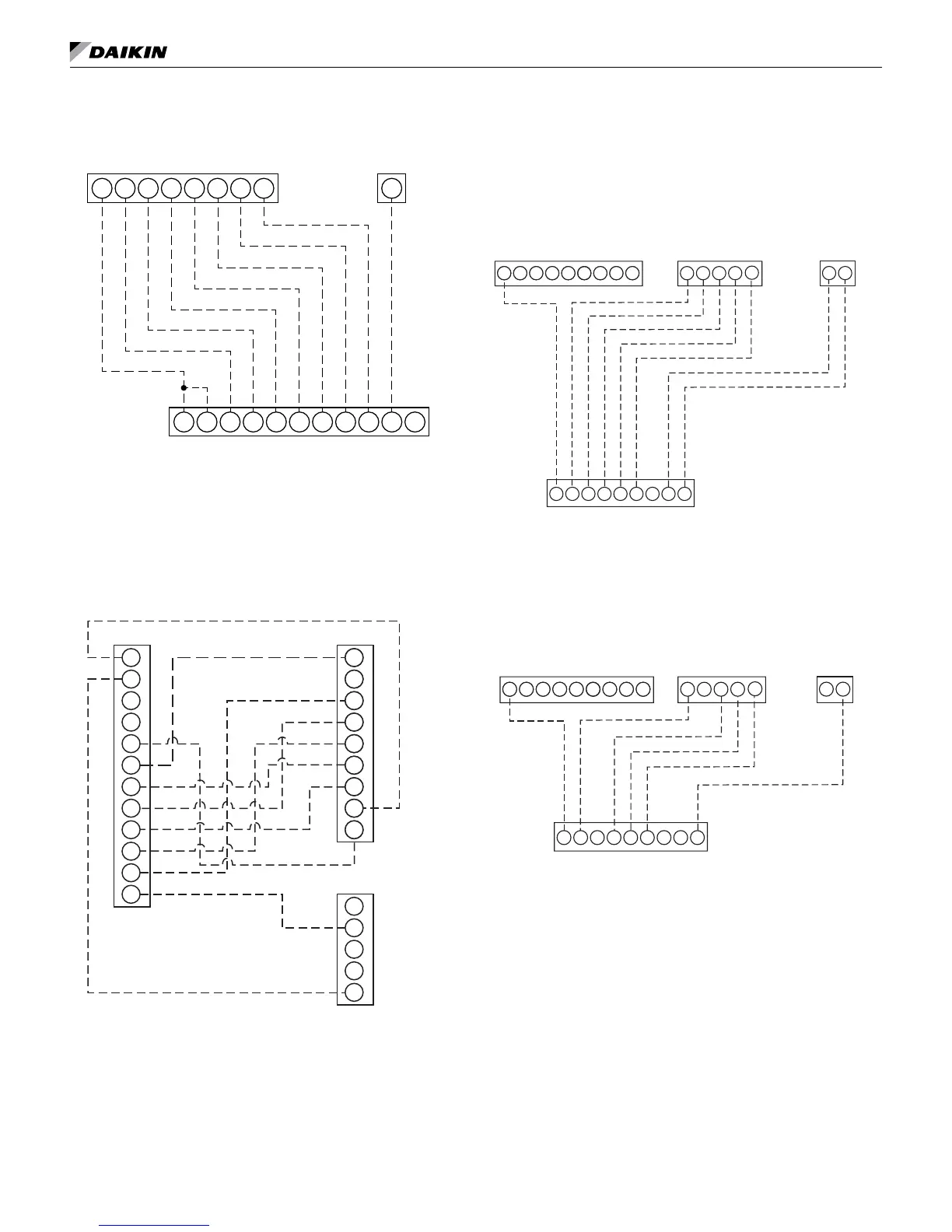
Programmable Electronic Thermostat
Hardwired – 1 Heat/1 Cool, Auto Changeover
Fan Speed Control – P/N 668811301
W2W1Y2Y1GCR A
W1Y2Y1GCRHRC W2 G2A
G2
MicroTech III Controller Terminals TB2
Programmable Thermostat Terminals
Terminal Strip
Notes: Includes thermostat and wall plate. Refer to IO
manual 668811301.
Non-Programmable Electronic Thermostat
2 Heat/2 Cool, Auto Changeover, Hardwired –
P/N 910121746 & P/N 910121748
L
S1
S2
R
C
W1
Y1
W2
Y2
G
A
O
O
G
Y1
Y2
W1
W2
A
R
C
4
3
2
1
5
O
G
Y1
Y2
W1
W2
A
R
C
TB2
WSHP MicroTech III Controlle
Terminals TB1 and TB2
TB1
Thermostat
Terminal
Notes: Includes thermostat and wall plate. Refer to IO
manuals 910121746 or 910121748.
*When remote reset of a lockout condition is re-
quired at the wall thermostat, it will be necessary to
utilize a conductor between terminal "O" on the wall
thermostat to "TB1 terminal 4" on the MicroTech III
unit controller (non-programmable stat only).
Sensors Used With Vertical Stack Units
– Building Automated System (BAS)
Operation – Wiring
6-Button Digitally Adjustable Display Sensor –
P/N 910121754
1
R
24
E
U65
3
O
G
Y1
Y2
W2
A
R
2
Y1
Y2
W1
W2
R
MicroTech III
Controller
Terminals TB2
MicroTech III
Controller
Terminals TB1
CG
O
A
1
U
MicroTech III
Controller
Terminals TB3
E
Digitally Adjustable Room
Temperature Sensor
4
3
5
4-Button Digitally Adjustable Display Sensor –
P/N 910152147
1
R
24
E
U65
3
O
G
Y1
Y2
W2
A
R
2
Y1
Y2
W1
W2
RCG
O
A
1
U
E
4
3
5
MicroTech III
Controller
Terminals TB2
MicroTech III
Controller
Terminals TB1
MicroTech III
Controller
Terminals TB3
Digitally Adjustable Room
Temperature Sensor