90 • Technical Specifications Genie Monochrome Series-GigE Vision Camera
Notes:
Genie supports a screw lock Ethernet cable (see "
Ruggedized RJ45 Ethernet Cables" on page 97).
For information on Genie lens requirements see "
Optical Considerations" on page 93.
Lens flange focal distance = 17.52 mm.
The camera top also has four mounting holes in identical locations.
Connectors
• A single RJ45 Ethernet connector for control and video data to the host Gigabit NIC. Genie is available with
an industrial case supporting a screw lock Ethernet cable (see "
Ruggedized RJ45 Ethernet Cables" on page 97).
• A single 12-pin Hirose male connector for power, trigger and strobe signals. The suggested female cable
mating connector is Hirose model HR10A-10P-12S.
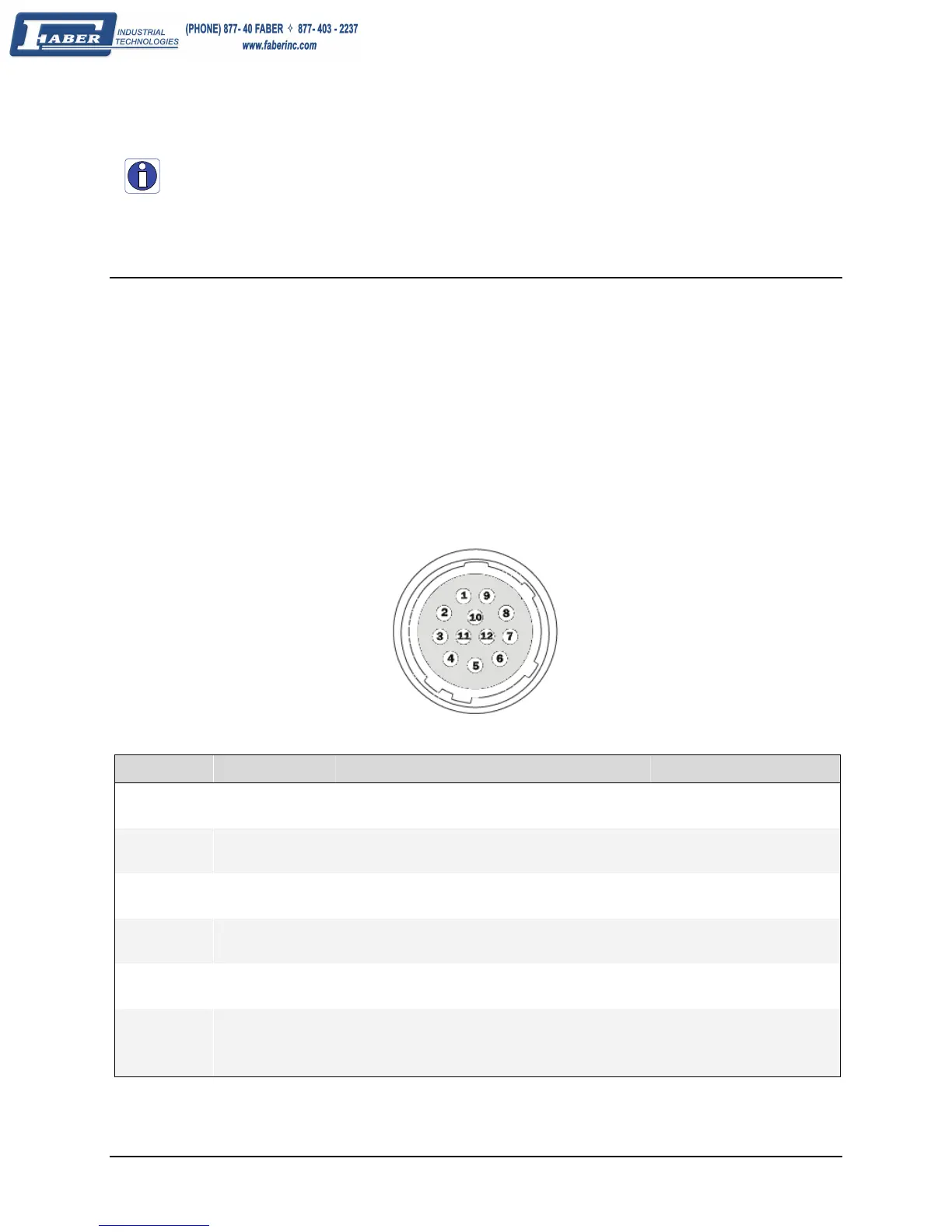
12-Pin Hirose Connector Signal Details
The following figure shows the pinout identification when looking at the Genie camera 12-pin male Hirose
connector. The table below the figure lists the Genie I/O signal specifications.
Pin Direction Genie Signal (see details below) Notes
1 - Power GND
2 - +12V DC power supply 10% tolerance
3 Out Output 1 -
4 Out Output 1 +
5 In Input 1 - RS422- or TTL GND
6 In Input 1 + RS422+ or TTL
7 Out Output 2 + / Strobe +
8 Out Output 2 - / Strobe -
9 - Reserved
10 - Reserved
11 In Input 2 + RS422+ or TTL
12 In Input 2 - RS422- or TTL GND
shell / shield via cable shield Genie chassis connects to supply earth ground improves EMI shielding