EasyManuals Logo

Dalsa Piranha 2 Series User Manual

Dalsa Piranha 2 Series
86 pages
To Next Page IconTo Next Page
To Previous Page IconTo Previous Page
Page #15 background imageLoading...
Page #15 background image
15 Piranha 2 Users Manual
03-032-00493-14 Teledyne DALSA
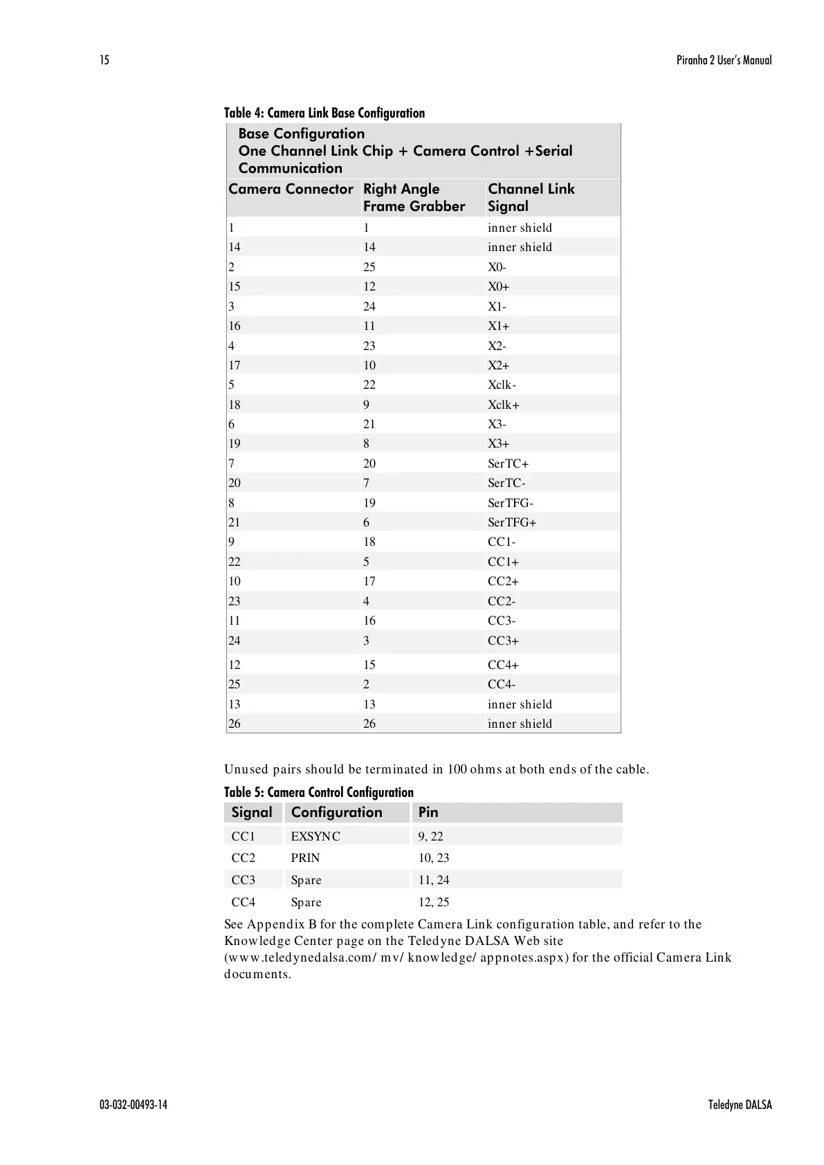
Table 4: Camera Link Base Configuration
Base Configuration
One Channel Link Chip + Camera Control +Serial
Communication
Camera Connector
Right Angle
Frame Grabber
Channel Link
Signal
1
1
inner shield
14
14
inner shield
2
25
X0-
15
12
X0+
3
24
X1-
16
11
X1+
4
23
X2-
17
10
X2+
5
22
Xclk-
18
9
Xclk+
6
21
X3-
19
8
X3+
7
20
SerTC+
20
7
SerTC-
8
19
SerTFG-
21
6
SerTFG+
9
18
CC1-
22
5
CC1+
10
17
CC2+
23
4
CC2-
11
16
CC3-
24
3
CC3+
12
15
CC4+
25
2
CC4-
13
13
inner shield
26
26
inner shield
Unused pairs should be terminated in 100 ohms at both ends of the cable.
Table 5: Camera Control Configuration
Signal
Configuration
Pin
CC1
EXSYNC
9, 22
CC2
PRIN
10, 23
CC3
Spare
11, 24
CC4
Spare
12, 25
See Appendix B for the complete Camera Link configuration table, and refer to the
Knowledge Center page on the Teledyne DALSA Web site
(www.teledynedalsa.com/ mv/ knowledge/ appnotes.aspx) for the official Camera Link
documents.
All manuals and user guides at all-guides.com

Table of Contents

Questions and Answers:

Question and Answer IconNeed help?

Do you have a question about the Dalsa Piranha 2 Series and is the answer not in the manual?

Dalsa Piranha 2 Series Specifications

General IconGeneral
BrandDalsa
ModelPiranha 2 Series
CategorySecurity Camera
LanguageEnglish

Related product manuals