21 Piranha 2 User’s Manual
03-032-00493-14 Teledyne DALSA
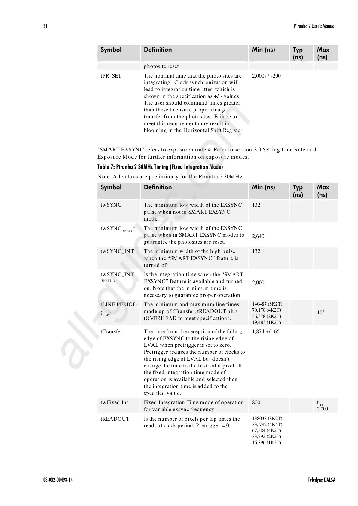
The nominal time that the photo sites are
integrating. Clock synchronization will
lead to integration time jitter, which is
shown in the specification as +/ - values.
The user should command times greater
than these to ensure proper charge
transfer from the photosites. Failure to
meet this requirement may result in
blooming in the Horizontal Shift Register.
*SMART EXSYNC refers to exposure mode 4. Refer to section 3.9 Setting Line Rate and
Exposure Mode for further information on exposure modes.
Table 7: Piranha 2 30MHz Timing (Fixed Integration Mode)
Note: All values are preliminary for the Piranha 2 30MHz
The minimum low width of the EXSYNC
pulse when not in SMART EXSYNC
mode.
The minimum low width of the EXSYNC
pulse when in SMART EXSYNC modes to
guarantee the photosites are reset.
The minimum width of the high pulse
w hen the ―SMART EXSYNC‖ feature is
turned off
Is the integration tim e w hen the ―SMART
EXSYN C‖ featu re is available and tu rned
on. Note that the minimum time is
necessary to guarantee proper operation.
The minimum and maximum line times
made up of tTransfer, tREADOUT plus
tOVERHEAD to meet specifications.
140487 (8K2T)
70,170 (4K2T)
36,378 (2K2T)
19,483 (1K2T)
The time from the reception of the falling
edge of EXSYNC to the rising edge of
LVAL when pretrigger is set to zero.
Pretrigger reduces the number of clocks to
the rising edge of LVAL but d oesn’t
change the time to the first valid pixel. If
the fixed integration time mode of
operation is available and selected then
the integration time is added to the
specified value.
Fixed Integration Time mode of operation
for variable exsync frequency.
Is the number of pixels per tap times the
readout clock period. Pretrigger = 0.
138033 (8K2T)
33, 792 (4K4T)
67,584 (4K2T)
33,792 (2K2T)
16,896 (1K2T)
All manuals and user guides at all-guides.com
all-guides.com

 Loading...


