4.7.2 Attaching the E1h/E2h to the Pedestal
1. Lift the drive and position it on the pedestal.
There are 2 bolts in the rear of the pedestal that
slide into the 2 slotted holes in the rear of the
enclosure. Position the drive by adjusting the
bolts up or down. Loosely secure with 2 M10 nuts
and locking brackets. See Illustration 4.4.
2. Verify that there is 225 mm (9 in) top clearance
for air exhaust.
3. Verify that the air intake at the bottom front of
the unit is not obstructed.
4. Around the top of the pedestal, secure the
enclosure using 6 M10x30 fasteners. Refer to
Illustration 4.5. Loosely tighten each bolt until all
bolts are installed.
5. Fasten each bolt securely and torque to 19 Nm
(169 in-lb).
6. Torque the 2 M10 nuts at the rear of the
enclosure to 19 Nm (169 in-lb).
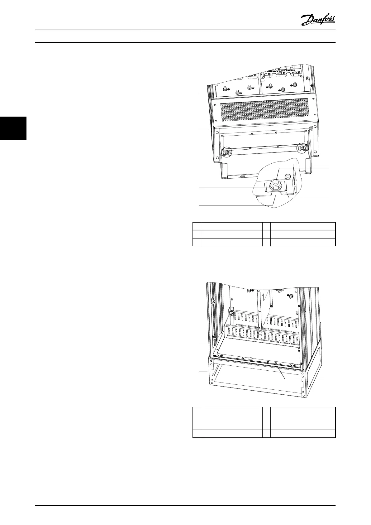
1 Enclosure 4 Slotted hole in enclosure
2 Pedestal 5 Bolt at rear of pedestal
3 M10 nut 6 Locking bracket
Illustration 4.4 Pedestal to Enclosure Back Mounting Points
1 Enclosure 3 M10x30 fasteners
(rear corner bolts not
shown)
2 Pedestal – –
Illustration 4.5 Pedestal to Enclosure Mounting Points
Mechanical Installation VLT® HVAC Drive FC 102
16 Danfoss A/S © 01/2017 All rights reserved. MG16O102
44