3.6 Local Control Panel (LCP)
130BF153.10
Auto
on
Reset
Hand
on
O
Status
Quick
Menu
Main
Menu
Alarm
Log
Back
Cancel
Info
OK
Status
1(1)
0.00 kW
0.0 Hz
On
Alarm
Warn.
0.00 A
0.0 %
2605 kWh
A1.1
A1.2
A1.3
A2
A3
B1
B2
B4
B3
C1
C2
C3
C4
C5
D1
D2
D3
E1
E2
E3
E4
O Remote Stop
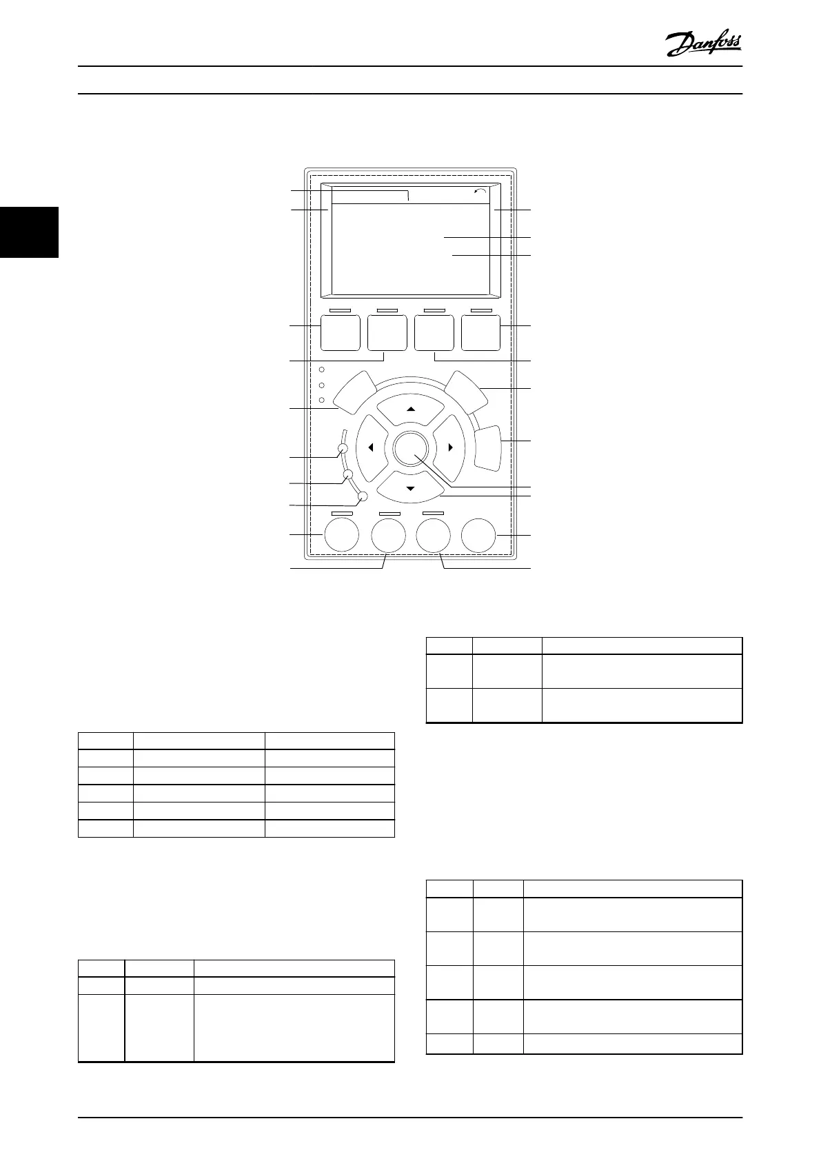
Illustration 3.4 Graphical Local Control Panel (LCP)
A. Display area
Each display readout has a parameter associated with it.
See Table 3.2. The information shown on the LCP can be
customized for specic applications. Refer to
chapter 6.3.1.2 Q1 My Personal Menu.
Callout Parameter number Default setting
A1.1 0-20 Reference [%]
A1.2 0-21 Motor current [A]
A1.3 0-22 Power [Kw]
A2 0-23 Frequency [Hz]
A3 0-24 kWh counter
Table 3.2 LCP Display Area
B. Menu keys
Menu keys are used to access the menu for setting up
parameters, toggling through status display modes during
normal operation, and viewing fault log data.
Callout Key Function
B1 Status Shows operational information.
B2 Quick Menu Allows access to parameters for initial
set-up instructions. Also provides
detailed application steps. Refer
to chapter 6.3.1.1 Quick Menu Mode.
Callout Key Function
B3 Main Menu Allows access to all parameters. Refer to
chapter 6.3.1.8 Main Menu Mode.
B4 Alarm Log Shows a list of current warnings and the
last 10 alarms.
Table 3.3 LCP Menu Keys
C. Navigation keys
Navigation keys are used for programming functions and
moving the display cursor. The navigation keys also
provide speed control in local (hand) operation. The
display brightness can be adjusted by pressing [Status] and
[
▲
]/[
▼
] keys.
Callout Key Function
C1 Back Reverts to the previous step or list in the
menu structure.
C2 Cancel Cancels the last change or command as
long as the display mode has not changed.
C3 Info Shows a denition of the function being
shown.
C4 OK Accesses parameter groups or enables an
option.
C5
▲
▼
◄ ►
Moves between items in the menu.
Table 3.4 LCP Navigation Keys
Product Overview VLT® HVAC Drive FC 102
10 Danfoss A/S © 01/2017 All rights reserved. MG16O102
33