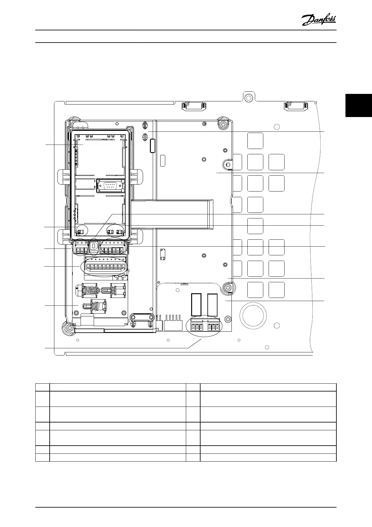
3.5 Control Shelf
130BF148.11
Remove Jumper to activate Safe Stop
12 13 18 19 27 29 32 33 20 37
39 42 50 53 54 55
61 68 69
1
3
4
12
9
8
RELAY 1 RELAY 2
01 02
03
04 05 06
2
6
10
7
5
11
13
1 LCP cradle (LCP not shown) 8 Control shelf
2 Bus terminal switch
(see chapter 5.8.5 Conguring RS485 Serial Communication)
9 USB port
3 Serial communication terminals (see Table 5.1) 10 Analog input switches A53/A54
(see chapter 5.8.10 Selecting Voltage/Current Input Signal)
4 Digital input/output terminals (see Table 5.2) 11 Analog input/output terminals (see Table 5.3)
5 Cable/EMC clamps 12 Brake resistor terminals, 104–106
(on power card underneath control shelf)
6 Relay 1 and relay 2 (see Illustration 5.19) 13 Power card (underneath the control shelf)
7 Control card (underneath LCP and control terminals) – –
Illustration 3.3 View of Control Shelf
Product Overview Operating Guide
MG16O102 Danfoss A/S © 01/2017 All rights reserved. 9
3 3