5.8 Control Wiring
All terminals to the control cables are inside the drive
below the LCP. To access, either open the door (E1h and
E2h) or remove the front panel (E3h and E4h).
5.8.1 Control Cable Routing
Tie down and route all control wires as shown in
Illustration 5.16. Remember to connect the shields in a
proper way to ensure optimum electrical immunity.
•
Isolate control wiring from high-power cables in
the drive.
•
When the drive is connected to a thermistor,
ensure that the thermistor control wiring is
shielded and reinforced/double insulated. A 24 V
DC supply voltage is recommended.
Fieldbus connection
Connections are made to the relevant options on the
control card. For more detail, see the relevant eldbus
instruction. The cable must be tied down and routed along
with other control wires inside the unit. See
Illustration 5.16.
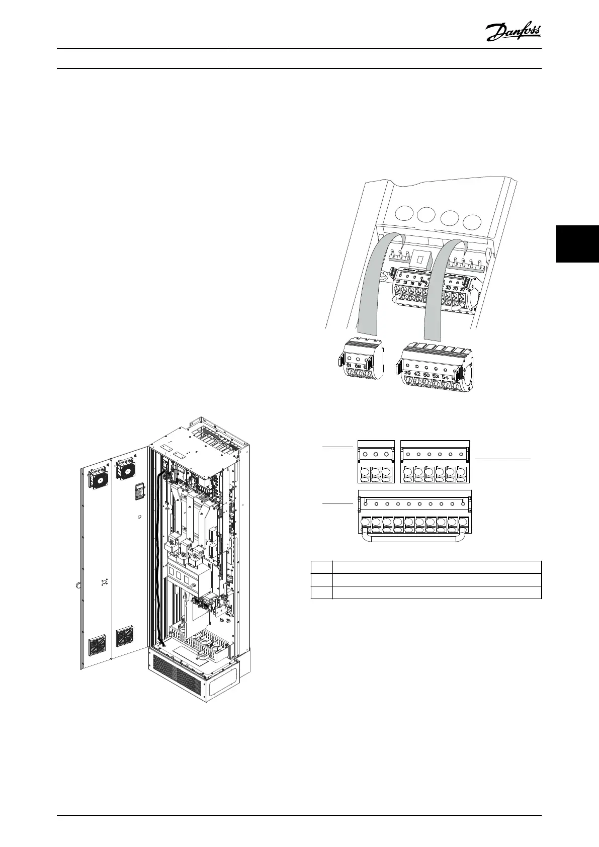
Illustration 5.16 Control Card Wiring Path
5.8.2 Control Terminal Types
Illustration 5.17 shows the removable drive connectors.
Terminal functions and default settings are summarized in
Table 5.1 – Table 5.3.
Illustration 5.17 Control Terminal Locations
12 13 18 19 27 29 32 33 20 37
39696861 42 50 53 54 55
130BF145.10
1
2
3
1 Serial communication terminals
2 Digital input/output terminals
3 Analog input/output terminals
Illustration 5.18 Terminal Numbers Located on the Connectors
Electrical Installation Operating Guide
MG16O102 Danfoss A/S © 01/2017 All rights reserved. 41
5 5