7 Wiring Conguration Examples
The examples in this section are intended as a quick
reference for common applications.
•
Parameter settings are the regional default values
unless otherwise indicated (selected in
parameter 0-03 Regional Settings).
•
Parameters associated with the terminals and
their settings are shown next to the drawings.
•
Required switch settings for analog terminals A53
or A54 are also shown.
NOTICE
When not using the optional STO feature, a jumper wire
is required between terminal 12 (or 13) and terminal 37
for the drive to operate with factory default
programming values.
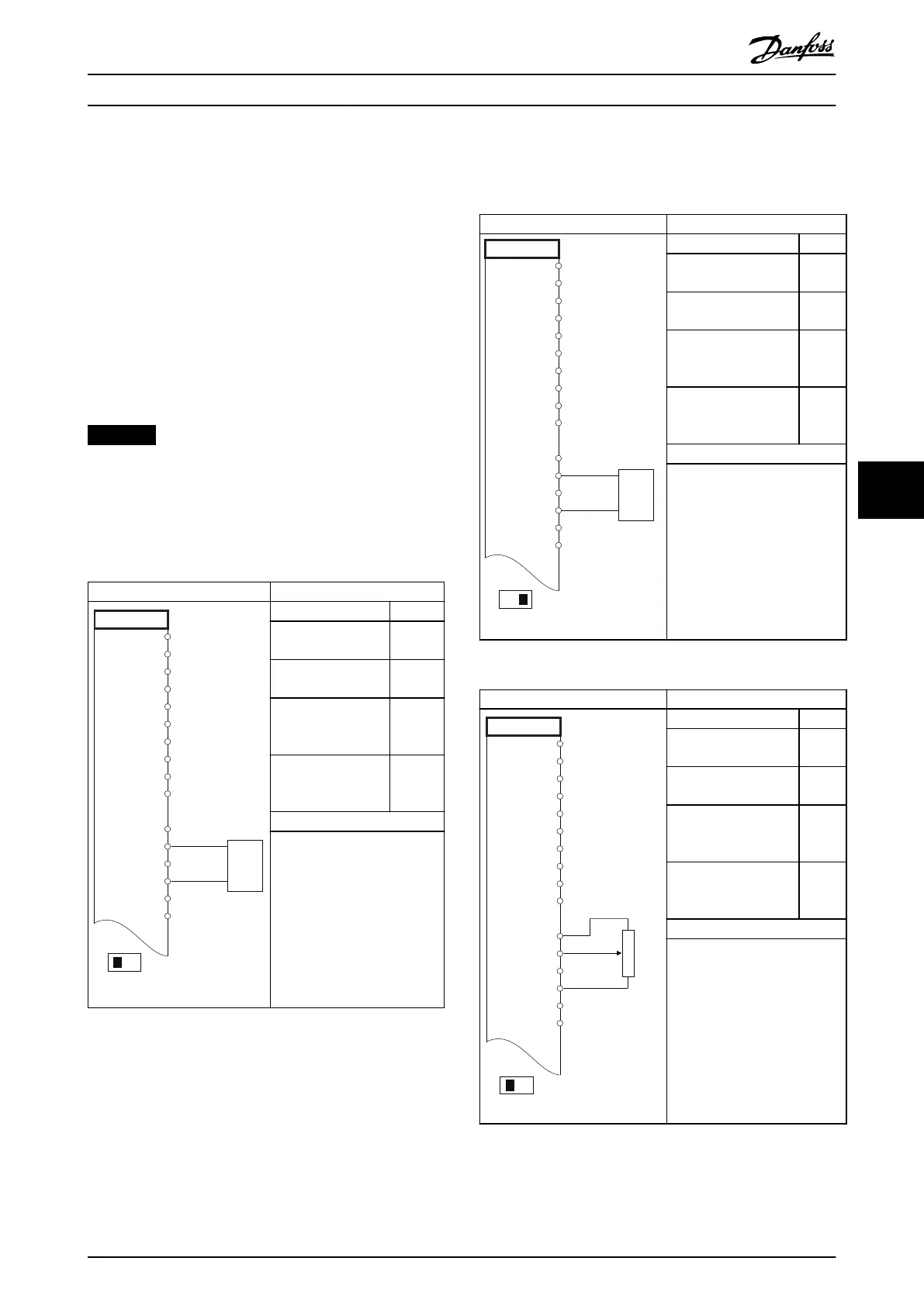
7.1 Wiring for Open-loop Speed Control
Parameters
FC
+24 V
+24 V
D IN
D IN
D IN
COM
D IN
D IN
D IN
D IN
+10
A IN
A IN
COM
A OUT
COM
12
13
18
19
20
27
29
32
33
37
50
53
54
55
42
39
A53
U - I
-10 - +10V
+
-
130BB926.10
Function Setting
Parameter 6-10 Termi
nal 53 Low Voltage
0.07 V*
Parameter 6-11 Termi
nal 53 High Voltage
10 V*
Parameter 6-14 Termi
nal 53 Low Ref./
Feedb. Value
0 Hz
Parameter 6-15 Termi
nal 53 High Ref./
Feedb. Value
50 Hz
* = Default value
Notes/comments:
Assumptions are 0 V DC input
= 0 Hz speed and 10 V DC
input = 50 Hz speed.
Table 7.1 Analog Speed Reference (Voltage)
Parameters
130BB927.10
FC
+24 V
+24 V
D IN
D IN
D IN
COM
D IN
D IN
D IN
D IN
+10
A IN
A IN
COM
A OUT
COM
12
13
18
19
20
27
29
32
33
37
50
53
54
55
42
39
A53
U - I
4 - 20mA
+
-
Function Setting
Parameter 6-12 Terminal
53 Low Current
4 mA*
Parameter 6-13 Terminal
53 High Current
20 mA*
Parameter 6-14 Terminal
53 Low Ref./Feedb.
Value
0 Hz
Parameter 6-15 Terminal
53 High Ref./Feedb.
Value
50 Hz
* = Default value
Notes/comments:
Assumptions are 4 mA input =
0 Hz speed and 20 mA input =
50 Hz speed.
Table 7.2 Analog Speed Reference (Current)
Parameters
FC
+24 V
+24 V
D IN
D IN
D IN
COM
D IN
D IN
D IN
D IN
+10
A IN
A IN
COM
A OUT
COM
12
13
18
19
20
27
29
32
33
37
50
53
54
55
42
39
A53
U - I
≈ 5kΩ
130BB683.10
Function Setting
Parameter 6-12 Terminal
53 Low Current
4 mA*
Parameter 6-13 Terminal
53 High Current
20 mA*
Parameter 6-14 Terminal
53 Low Ref./Feedb.
Value
0 Hz
Parameter 6-15 Terminal
53 High Ref./Feedb.
Value
50 Hz
* = Default value
Notes/comments:
Assumptions are 0 V DC input
= 0 RPM speed and 10 V DC
input = 1500 RPM speed.
Table 7.3 Speed Reference (Using a Manual Potentiometer)
Wiring Conguration Exampl... Operating Guide
MG16O102 Danfoss A/S © 01/2017 All rights reserved. 55
7 7