7.4 Wiring for a Motor Thermistor
WARNING
THERMISTOR INSULATION
Risk of personal injury or equipment damage.
•
To meet PELV insulation requirements, use only
thermistors with reinforced or double
insulation.
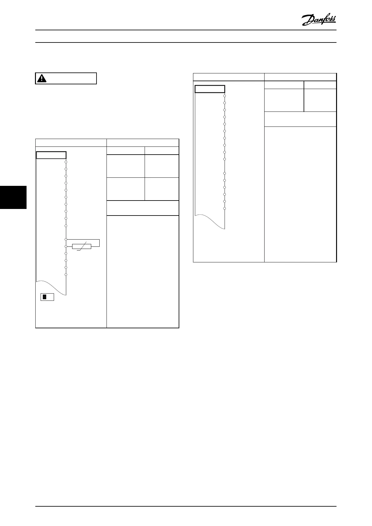
Parameters
130BB686.12
VLT
+24 V
+24 V
D IN
D IN
D IN
COM
D IN
D IN
D IN
+10 V
A IN
A IN
COM
A OUT
COM
12
13
18
19
20
27
29
32
33
50
53
54
55
42
39
A53
U - I
D IN
37
Function Setting
Parameter 1-90
Motor Thermal
Protection
[2] Thermistor
trip
Parameter 1-93
Thermistor
Resource
[1] Analog
input 53
* = Default value
Notes/comments:
If only a warning is desired, set
parameter 1-90 Motor Thermal
Protection to [1] Thermistor
warning.
Table 7.9 Motor Thermistor
7.5
Wiring for Regeneration
Parameters
FC
+24 V
+24 V
D IN
D IN
D IN
COM
D IN
D IN
D IN
D IN
+10
A IN
A IN
COM
A OUT
COM
12
13
18
19
20
27
29
32
33
37
50
53
54
55
42
39
130BD667.11
Function Setting
Parameter 1-90
Motor Thermal
Protection
100%*
* = Default value
Notes/comments:
To disable regeneration,
decrease parameter 1-90 Motor
Thermal Protection to 0%. If the
application uses motor brake
power and regeneration is not
enabled, the unit trips.
Table 7.10 Regeneration
Wiring Conguration Exampl... VLT® HVAC Drive FC 102
58 Danfoss A/S © 01/2017 All rights reserved. MG16O102
77