4.6 Lifting the Unit
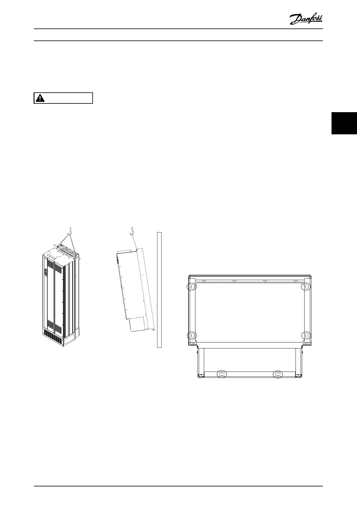
Always lift the drive using the dedicated lifting eyes. To
avoid bending the lifting holes, use a bar.
WARNING
RISK OF INJURY OR DEATH
Follow local safety regulations for lifting heavy weights.
Failure to follow recommendations and local safety
regulations can result in death or serious injury.
•
Ensure that the lifting equipment is in proper
working condition.
•
See chapter 3.2 Power Ratings, Weights, and
Dimensions for the weight of the dierent
enclosure types.
•
Maximum diameter for bar: 20 mm (0.8 in).
•
The angle from the top of the drive to the
lifting cable: 60° or greater.
Illustration 4.2 Recommended Lifting Method
4.7 E1h/E2h Mechanical Installation
The E1h and E2h enclosure size is intended only for oor
installation, and is shipped with a pedestal and a gland
plate. The pedestal and gland plate must be installed for
proper installation.
The pedestal is 200 mm (7.9 in) and has an opening in the
front to allow
airow necessary to cool the power
components of the drive.
The gland plate is necessary to provide cooling air to the
control components of the drive via the door fan, and to
maintain the IP21/Type 1 or IP54/Type 12 protection rating.
4.7.1 Securing the Pedestal to the Floor
The pedestal must be secured to the oor using 6 bolts
before installing the enclosure.
1. Determine proper placement of the unit,
concerning operating conditions and cable
access.
2. Access the mounting holes by removing the front
panel of the pedestal.
3. Set the pedestal on the oor and secure using 6
bolts through the mounting holes. Refer to the
circled areas in Illustration 4.3.
Illustration 4.3 Pedestal to Floor Mounting Points
Mechanical Installation Operating Guide
MG16O102 Danfoss A/S © 01/2017 All rights reserved. 15
4 4