It may be necessary to contact the Danfoss supplier or
service department. Note the code number for further
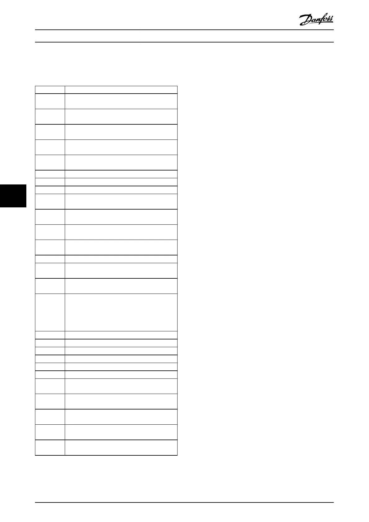
troubleshooting directions
Number Text
0 The serial port cannot be initialized. Contact the
Danfoss supplier or Danfoss service department.
256–258 The power EEPROM data is defective or too old.
Replace the power card.
512–519 Internal fault. Contact the Danfoss supplier or
Danfoss service department.
783 Parameter value outside of minimum/maximum
limits.
1024–1284 Internal fault. Contact the Danfoss supplier or
Danfoss service department.
1299 The option software in slot A is too old.
1300 The option software in slot B is too old.
1302 The option software in slot C1 is too old.
1315 The option software in slot A is not supported/
allowed.
1316 The option software in slot B is not supported/
allowed.
1318 The option software in slot C1 is not supported/
allowed.
1379–2819 Internal fault. Contact the Danfoss supplier or
Danfoss service department.
1792 Hardware reset of digital signal processor.
1793 Motor-derived parameters not transferred correctly
to the digital signal processor.
1794 Power data not transferred correctly at power-up
to the digital signal processor.
1795 The digital signal processor has received too many
unknown SPI telegrams. The frequency converter
also uses this fault code if the MCO does not
power up correctly. This situation can occur due to
poor EMC protection or improper grounding.
1796 RAM copy error.
2561 Replace the control card.
2820 LCP stack overow.
2821 Serial port overow.
2822 USB port overow.
3072–5122 Parameter value is outside its limits.
5123 Option in slot A: Hardware incompatible with the
control board hardware.
5124 Option in slot B: Hardware incompatible with the
control board hardware.
5125 Option in slot C0: Hardware incompatible with the
control board hardware.
5126 Option in slot C1: Hardware incompatible with the
control board hardware.
5376–6231 Internal fault. Contact the Danfoss supplier or
Danfoss service department.
Table 7.1 Internal Fault Codes
ALARM 39, Heat sink sensor
No feedback from the heat sink temperature sensor.
The signal from the IGBT thermal sensor is not available on
the power card. The problem could be on the power card,
on the gatedrive card, or the ribbon cable between the
power card and gatedrive card.
WARNING 40, Overload of digital output terminal 27
Check the load connected to terminal 27 or remove the
short-circuit connection. Check parameter 5-00 Digital I/O
Mode and parameter 5-01 Terminal 27 Mode.
WARNING 41, Overload of digital output terminal 29
Check the load connected to terminal 29 or remove the
short-circuit connection. Also check parameter 5-00 Digital
I/O Mode and parameter 5-02 Terminal 29 Mode.
WARNING 42, Overload of digital output on X30/6 or
overload of digital output on X30/7
For terminal X30/6, check the load connected to terminal
X30/6 or remove the short-circuit connection. Also check
parameter 5-32 Term X30/6 Digi Out (MCB 101) (VLT
®
General Purpose I/O MCB 101).
For terminal X30/7, check the load connected to terminal
X30/7 or remove the short-circuit connection. Check
parameter 5-33 Term X30/7 Digi Out (MCB 101) (VLT
®
General Purpose I/O MCB 101).
ALARM 43, Ext. supply
VLT
®
Extended Relay Option MCB 113 is mounted without
external 24 V DC. Either connect a 24 V DC external supply
or specify that no external supply is used via
parameter 14-80 Option Supplied by External 24VDC, [0] No.
A change in parameter 14-80 Option Supplied by External
24VDC requires a power cycle.
ALARM 45, Earth fault 2
Ground fault.
Troubleshooting
•
Check for proper grounding and loose
connections.
•
Check for proper wire size.
•
Check the motor cables for short circuits or
leakage currents.
ALARM 46, Power card supply
The supply on the power card is out of range. Another
reason can be a defective heat sink fan.
There are 3 supplies generated by the switch mode supply
(SMPS) on the power card:
•
24 V.
•
5 V.
•
±18 V.
When powered with VLT
®
24 V DC Supply MCB 107, only
the 24 V and 5 V supplies are monitored. When powered
with 3-phase mains voltage, all 3 supplies are monitored.
Troubleshooting
•
Check for a defective power card.
•
Check for a defective control card.
Maintenance, Diagnostics, a...
VLT
®
AutomationDrive FC 301/302
28 Danfoss A/S © 05/2018 All rights reserved. MG33AT02
77