1.4.2 Exploded Views
1
2
3
4
5
6
7
8
9
10
11
12
13
16
17
18
19
14
6
FAN MOUNTING
QDF-30
DC-
DC+
Remove jumper to activate Safe Stop
Max. 24 Volt !
12
13 18 19 27 29 32
33
20
37
06 05 04
03 02 01
1
3
5
20
9
6
13
15
14
6
18
11
10
16, 17
19
14
7
8
4
2
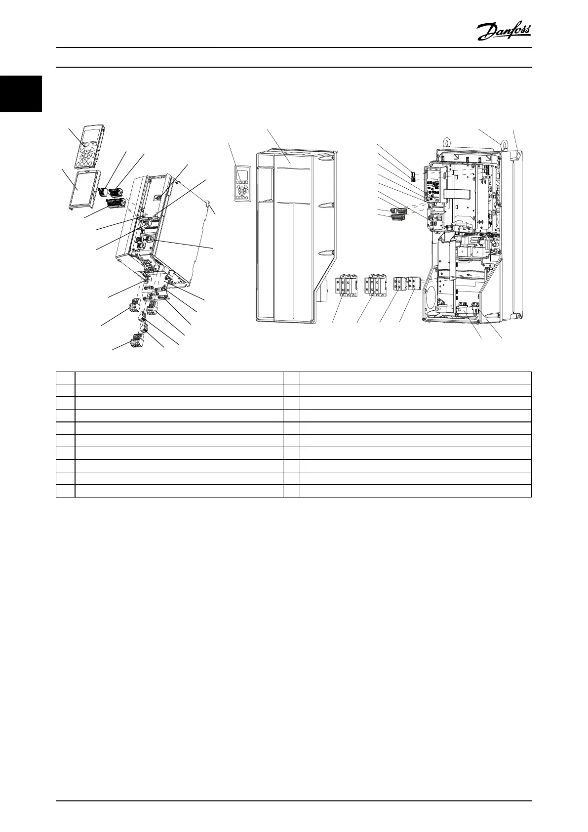
1 Local control panel (LCP) 11 Relay 2 (04, 05, 06)
2 Cover 12 Lifting ring
3 RS485 eldbus connector 13 Mounting slot
4 Digital input/output connector 14 Ground connection (PE)
5 Digital input/output connector 15 Cable shield connector
6 Shielded cable grounding and relief 16 Brake terminal (-81, +82)
7 USB connector 17 Load sharing terminal (-88, +89)
8 RS485 termination switch 18 Motor terminals 96 (U), 97 (V), 98 (W)
9 DIP switch for A53 and A54 19 Mains input terminals 91 (L1), 92 (L2), 93 (L3)
10 Relay 1 (01, 02, 03) 20 LCP connector
Illustration 1.1 Exploded View Enclosure Size A, IP20 (left), and Enclosure Size C, IP55/IP66 (right)
Introduction
VLT
®
AutomationDrive FC 301/302
4 Danfoss A/S © 05/2018 All rights reserved. MG33AT02
11