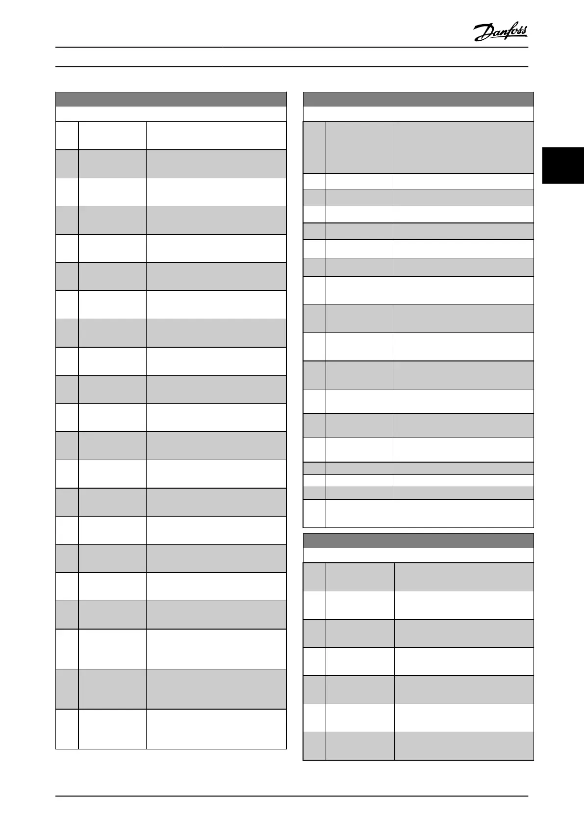
13-01 Start Event
Option: Function:
[18] Reversing
See parameter group 5-3* Digital
Outputs for further description.
[19] Warning
See parameter group 5-3* Digital
Outputs for further description.
[20] Alarm (trip)
See parameter group 5-3* Digital
Outputs for further description.
[21] Alarm (trip lock)
See parameter group 5-3* Digital
Outputs for further description.
[22] Comparator 0 Use the result of comparator 0 in the
logic rule.
[23] Comparator 1 Use the result of comparator 1 in the
logic rule.
[24] Comparator 2 Use the result of comparator 2 in the
logic rule.
[25] Comparator 3 Use the result of comparator 3 in the
logic rule.
[26] Logic rule 0 Use the result of logic rule 0 in the
logic rule.
[27] Logic rule 1 Use the result of logic rule 1 in the
logic rule.
[28] Logic rule 2 Use the result of logic rule 2 in the
logic rule.
[29] Logic rule 3 Use the result of logic rule 3 in the
logic rule.
[33] Digital input DI18 Use the value of DI18 in the logic rule
(High=TRUE).
[34] Digital input DI19 Use the value of DI19 in the logic rule
(High=TRUE).
[35] Digital input DI27 Use the value of DI27 in the logic rule
(High=TRUE).
[36] Digital input DI29 Use the value of DI29 in the logic rule
(High=TRUE).
[37] Digital input DI32 Use the value of DI32 in the logic rule
(High=TRUE).
[38] Digital input DI33 Use the value of DI33 in the logic rule
(High=TRUE).
[39] Start command This event is TRUE if the frequency
converter is started (either via digital
input, eldbus or other).
[40] Drive stopped This event is TRUE if the frequency
converter is stopped or coasted (either
via digital input, eldbus or other).
[41] Reset Trip This event is TRUE if the frequency
converter is tripped (but not trip-
locked) and [Reset] is pressed.
13-01 Start Event
Option: Function:
[42] Auto Reset Trip This event is TRUE if the frequency
converter is tripped (but not trip-
locked) and an automatic reset is
issued.
[43] OK Key This event is TRUE if [OK] is pressed.
[44] Reset Key This event is TRUE if [Reset] is pressed.
[45] Left Key
This event is TRUE if [◄] is pressed.
[46] Right Key
This event is TRUE if [►] is pressed.
[47] Up Key
This event is TRUE if [
▲
] is pressed.
[48] Down Key
This event is TRUE if [
▼
] is pressed.
[50] Comparator 4 Use the result of comparator 4 in the
logic rule.
[51] Comparator 5 Use the result of comparator 5 in the
logic rule.
[60] Logic rule 4 Use the result of logic rule 4 in the
logic rule.
[61] Logic rule 5 Use the result of logic rule 5 in the
logic rule.
[76] Digital Input x30
2
[77] Digital Input x30
3
[78] Digital Input x30
4
[90] ECB Drive Mode
[91] ECB Bypass Mode
[92] ECB Test Mode
[100] Fire Mode
See 13-15 RS-FF Operand S, 13-16 RS-FF
Operand R.
13-02 Stop Event
Option: Function:
Select the boolean (TRUE or FALSE)
input to deactivate smart logic control.
[0] False Enters the xed value of FALSE in the
logic rule.
[1] True Enters the xed value TRUE in the
logic rule.
[2] Running
See parameter group 5-3* Digital
Outputs for further description.
[3] In range
See parameter group 5-3* Digital
Outputs for further description.
[4] On reference
See parameter group 5-3* Digital
Outputs for further description.
[5] Torque limit
See parameter group 5-3* Digital
Outputs for further description.
Parameter Descriptions Programming Guide
MG11CE02 Danfoss A/S © 03/2015 All rights reserved. 107
3 3
 Loading...


