13-02 Stop Event
Option: Function:
[61] Logic rule 5 Use the result of logic rule 5 in the
logic rule.
[70] SL Time-out 3 Use the result of timer 3 in the logic
rule.
[71] SL Time-out 4 Use the result of timer 4 in the logic
rule.
[72] SL Time-out 5 Use the result of timer 5 in the logic
rule.
[73] SL Time-out 6 Use the result of timer 6 in the logic
rule.
[74] SL Time-out 7 Use the result of timer 7 in the logic
rule.
[76] Digital Input x30
2
[77] Digital Input x30
3
[78] Digital Input x30
4
[80] No Flow
[81] Dry Pump
[82] End of Curve
[83] Broken Belt
[90] ECB Drive Mode
[91] ECB Bypass Mode
[92] ECB Test Mode
[100] Fire Mode
See 13-15 RS-FF Operand S, 13-16 RS-FF
Operand R.
13-03 Reset SLC
Option: Function:
[0] * Do not reset
SLC
Retains programmed settings in all
parameter group 13-** Smart Logic Control.
[1] Reset SLC Resets all parameters in parameter group
13-** Smart Logic Control to default settings.
3.13.3 13-1* Comparators
Comparators are used for comparing continuous variables
(that is output frequency, output current, analog input and
so on.) to xed preset values.
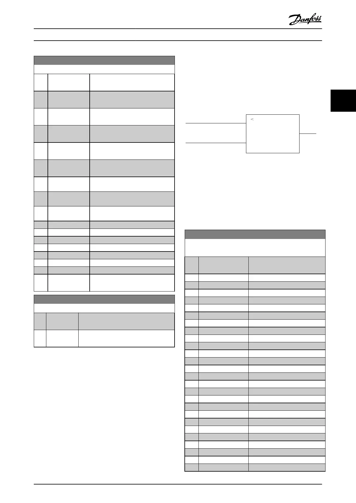
Par. 13-11
Comparator Operator
=
TRUE longer than.
. . .
. . .
Par. 13-10
Comparator Operand
Par. 13-12
Comparator Value
130BB672.10
Illustration 3.35 Comparators
There are digital values that are compared to xed time
values. See explanation in 13-10 Comparator Operand.
Comparators are evaluated once in each scan interval. Use
the result (TRUE or FALSE) directly. All parameters in this
parameter group are array parameters with index 0 to 5.
Select index 0 to programme comparator 0, select index 1
to programme comparator 1, and so on.
13-10 Comparator Operand
Array [4]
Option: Function:
Select the variable to be
monitored by the comparator.
[0] DISABLED
[1] Reference %
[2] Feedback %
[3] Motor speed
[4] Motor Current
[5] Motor torque
[6] Motor power
[7] Motor voltage
[8] DC-link voltage
[9] Motor Thermal
[10] Drive thermal
[11] Heat sink temp.
[12] Analog input AI53
[13] Analog input AI54
[14] Analog input AIFB10
[15] Analog input AIS24V
[17] Analog input AICCT
[18] Pulse input FI29
[19] Pulse input FI33
[20] Alarm number
[21] Warning number
[22] Analog input x30 11
[23] Analog input x30 12
[24] Sensorless Flow
[25] Sensorless Pressure
[30] Counter A
Parameter Descriptions Programming Guide
MG11CE02 Danfoss A/S © 03/2015 All rights reserved. 109
3 3
 Loading...


