3.14 Parameters: 14-** Main Menu - Special
Functions
3.14.1 14-0* Inverter Switching
14-00 Switching Pattern
Option: Function:
Select the switching pattern: 60° AVM or SFAVM.
[0] 60 AVM
[1] SFAVM
14-01 Switching Frequency
Option: Function:
Select the inverter switching frequency. Changing
the switching frequency can help reduce acoustic
noise from the motor.
NOTICE
The output frequency value of the
frequency converter must never exceed
1/10 of the switching frequency. When the
motor is running, adjust the switching
frequency in parameter 14-01 Switching
Frequency until the motor is as noiseless as
possible. See also
parameter 14-00 Switching Pattern. For
information about derating, see the
relevant design guide.
[0] 1.0 kHz
[1] 1.5 kHz
[2] 2.0 kHz
[3] 2.5 kHz
[4] 3.0 kHz
[5] 3.5 kHz
[6] 4.0 kHz
[7] 5.0 kHz
[8] 6.0 kHz
[9] 7.0 kHz
[10] 8.0 kHz
[11] 10.0 kHz
[12] 12.0kHz
[13] 14.0 kHz
[14] 16.0kHz
14-03 Overmodulation
Option: Function:
[0] * O Selects no overmodulation of the output voltage to
avoid torque ripple on the motor shaft.
[1] On The overmodulation function generates an extra
voltage of up to 8% of U
max
output voltage without
overmodulation. This extra voltage results in an extra
torque of 10-12% in the middle of the oversyncronous
range (from 0% at nominal speed rising to approxi-
mately 12% at double nominal speed).
14-04 PWM Random
Option: Function:
[0] * O No change of the acoustic motor switching noise.
[1] On Transforms the acoustic motor switching noise from a
clear ringing tone to a less noticeable white noise. This
is achieved by slightly and randomly altering the
synchronism of the pulse width modulated output
phases.
3.14.2 14-1* Mains On/O
Parameters for conguring mains failure monitoring and
handling.
14-10 Mains Failure
Option: Function:
Select the function at which the frequency
converter must act, when the threshold set in
parameter 14-11 Mains Voltage at Mains Fault has
been reached or a Mains Failure Inverse
command is activated via one of the digital
inputs (parameter group 5-1* Digital Inputs).
Only selection [0] No function, [3] Coasting or [6]
Alarm is available when parameter 1-10 Motor
Construction is set to [1] PM non-salient SPM
[0]
*
No
function
The energy left in the capacitor bank is used to
drive the motor, but is discharged.
[1] Ctrl.
ramp-
down
The frequency converter performs a controlled
ramp down. Parameter 2-10 Brake Function must
be set to [0] O.
[3] Coasting The inverter turns o and the capacitor bank
backs up the control card. Backing up control
card ensures a faster restart when mains
reconnected (at short power zags).
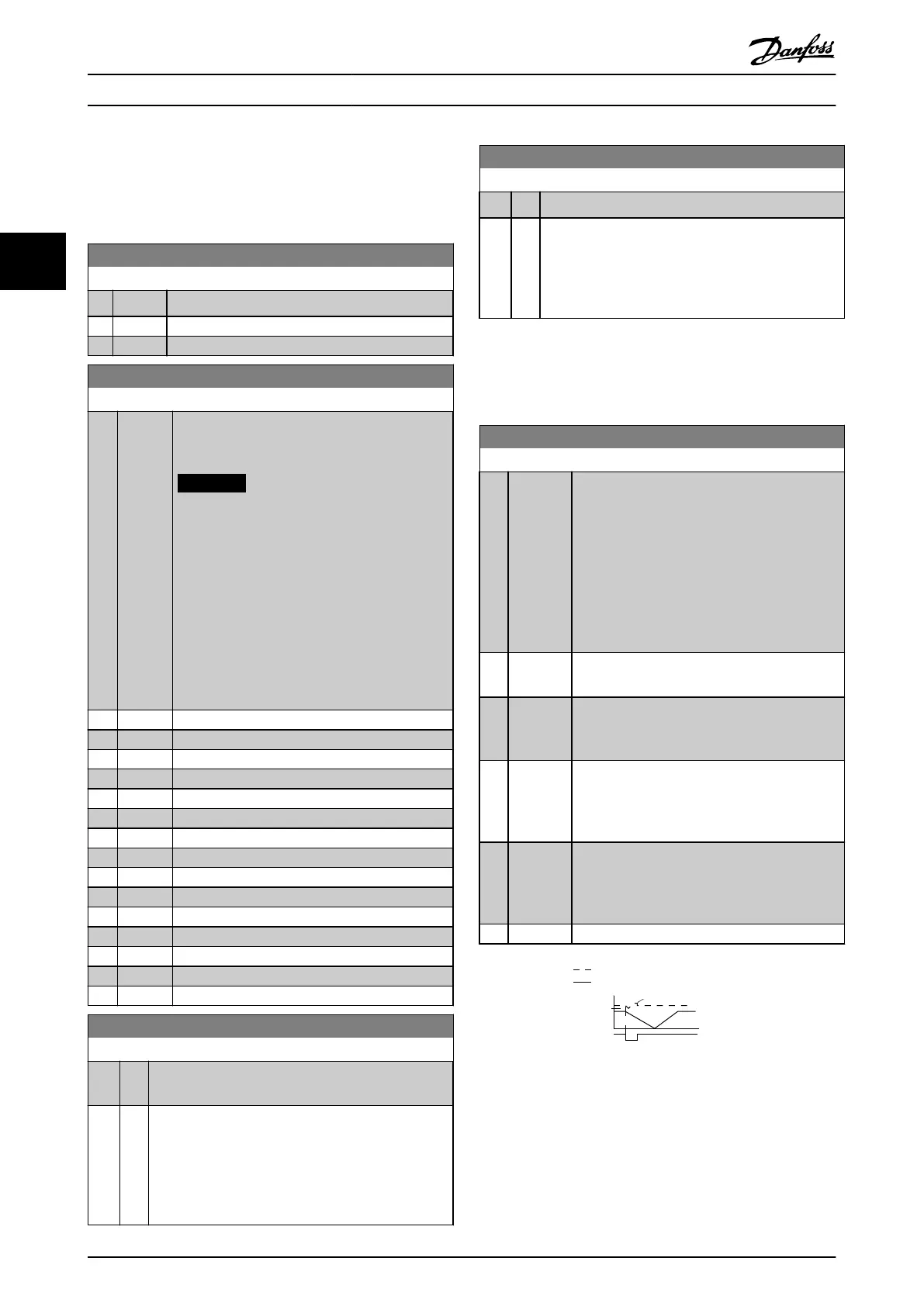
[4] Kinetic
back-up
The frequency converter rides through by
controlling speed for generative operation of the
motor utilising the moment of inertia of the
system as long as sucient energy is present.
[6] Alarm
DC Voltage
Output Speed rpm
Over Voltage Control Level
Mains
Time
130BT101.10
Par 14-11
Illustration 3.37 Controlled Ramp Down - Short Mains Failure.
Parameter Descriptions
VLT
®
HVAC Drive FC 102
118 Danfoss A/S © 03/2015 All rights reserved. MG11CE02
33
 Loading...


