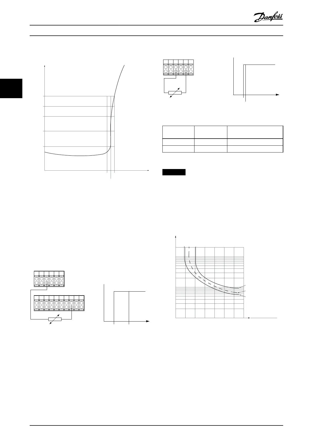
3.3.13.1 PTC Thermistor Connection
1330
550
250
-20 °C
175HA183.11
4000
3000
R
(Ω)
nominal
nominal -5 °C nominal +5 °C
[°C]
Illustration 3.11 PTC Prole
Using a digital input and 10 V as supply:
Example: The frequency converter trips when the motor
temperature is too high.
Parameter set-up:
•
Set 1-90 Motor Thermal Protection to [2] Thermistor
Trip.
•
Set parameter 1-93 Thermistor Source to [6] Digital
Input.
PTC / Thermistor
R
OFF
ON
<800 Ω
+10V
130BA152.10
>2.7 kΩ
12 13 18 37322719 29 33 20
5550
39 42 53 54
Illustration 3.12 PTC Thermistor Connection - Digital Input
Using an analog input and 10 V as supply:
Example: The frequency converter trips when the motor
temperature is too high.
Parameter set-up:
•
Set 1-90 Motor Thermal Protection to [2] Thermistor
Trip.
•
Set parameter 1-93 Thermistor Source to [2] Analog
Input 54.
555039 42 53 54
R
<3.0 k Ω
>3.0 k Ω
+10V
130BA153.11
PTC / Thermistor
OFF
ON
Illustration 3.13 PTC Thermistor Connection - Analog Input
Input
digital/analog
Supply voltage Threshold
cut out values.
Digital 10 V
<800 Ω–>2.7 kΩ
Analog 10 V
<3.0 kΩ–>3.0 kΩ
Table 3.9 Threshold Cut Out Values
NOTICE
Check that the selected supply voltage follows the
specication of the used thermistor element.
3.3.13.2 ETR
The calculations estimate the need for a lower load at
lower speed due to less cooling from the fan incorporated
in the motor.
1.21.0 1.4
30
10
20
100
60
40
50
1.81.6 2.0
2000
500
200
400
300
1000
600
t [s]
175ZA052.12
f
OUT
= 2 x f
M,N
f
OUT
= 0.2 x f
M,N
f
OUT
= 1 x f
M,N
(par. 1-23)
I
MN
(par. 1-24)
I
M
Illustration 3.14 ETR Prole
Parameter Descriptions
VLT
®
HVAC Drive FC 102
52 Danfoss A/S © 03/2015 All rights reserved. MG11CE02
33
 Loading...


