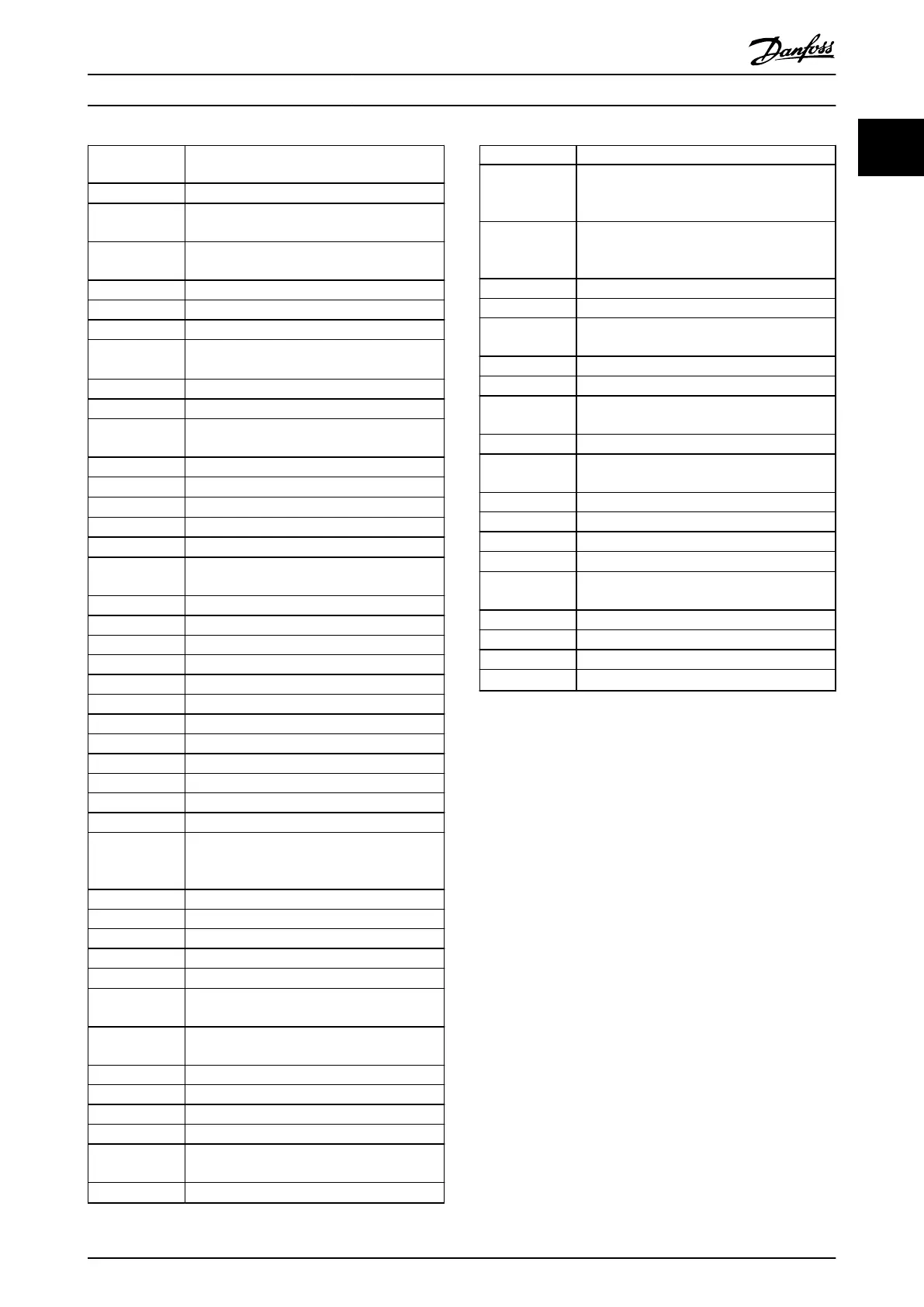
f
JOG
Motor frequency when jog function is
activated.
f
M
Motor frequency
f
MAX
Maximum output frequency, the frequency
converter applies on its output.
f
MIN
Minimum motor frequency from the frequency
converter
f
M,N
Nominal motor frequency
FC Frequency converter
g Gramme
Hiperface
®
Hiperface
®
is a registered trademark by
Stegmann
HO High overload
hp Horse power
HTL HTL encoder (10–30 V) pulses - High-voltage
transistor logic
Hz Hertz
I
INV
Rated inverter output current
I
LIM
Current limit
I
M,N
Nominal motor current
I
VLT,MAX
Maximum output current
I
VLT,N
Rated output current supplied by the
frequency converter
kHz Kilohertz
LCP Local control panel
lsb Least signicant bit
m Meter
mA Milliampere
MCM Mille circular mil
MCT Motion control tool
mH Inductance in milli Henry
min Minute
mm Millimeter
ms Millisecond
msb Most signicant bit
η
VLT
Eciency of the frequency converter dened
as ratio between power output and power
input.
nF Capacitance in nano Farad
NLCP Numerical local control panel
Nm Newton meter
NO Normal overload
n
s
Synchronous motor speed
Online/Oine
Parameters
Changes to online parameters are activated
immediately after the data value is changed.
P
br,cont.
Rated power of the brake resistor (average
power during continuous braking).
PCB Printed circuit board
PCD Process data
PDS Power drive system: a CDM and a motor
PELV Protective extra low voltage
P
m
Frequency converter nominal output power as
high overload (HO).
P
M,N
Nominal motor power
PM motor Permanent magnet motor
Process PID PID (Proportional Integrated Dierential)
regulator that maintains the desired speed,
pressure, temperature, and so on.
R
br,nom
Nominal resistor value that ensures a brake
power on motor shaft of 150/160% for 1
minute
RCD Residual current device
Regen Regenerative terminals
R
min
Minimum permissible brake resistor value by
frequency converter
RMS Root mean square
RPM Revolutions per minute
R
rec
Recommended brake resistor resistance of
Danfoss brake resistors
s Second
SFAVM Stator ux-oriented asynchronous vector
modulation
STW Status word
SMPS Switch mode power supply
THD Total harmonic distortion
T
LIM
Torque limit
TTL TTL encoder (5 V) pulses - transistor transistor
logic
U
M,N
Nominal motor voltage
V Volts
VT Variable torque
VVC
+
Voltage vector control plus
Table 1.2 Abbreviations
Conventions
Numbered lists indicate procedures.
Bullet lists indicate other information and description of
illustrations.
Italicised text indicates:
•
Cross reference
•
Link
•
Footnote
•
Parameter name, parameter group name,
parameter option
All dimensions are in mm (inch).
* indicates a default setting of a parameter.
•
VLT
®
HVAC Drive FC 102 Operating Instructions
provides information on mechanical and electrical
installation of the frequency converter.
•
VLT
®
HVAC Drive FC 102 Design Guide holds all
technical information about the frequency
converter, customer design, and applications.
•
VLT
®
HVAC Drive FC 102 Programming Guide
provides information on how to programme and
includes complete parameter descriptions.
•
Application Note, Temperature Derating Guide.
Introduction
Programming Guide
MG11CE02 Danfoss A/S © 03/2015 All rights reserved. 5
1
1
 Loading...


