Setting in
parameter group
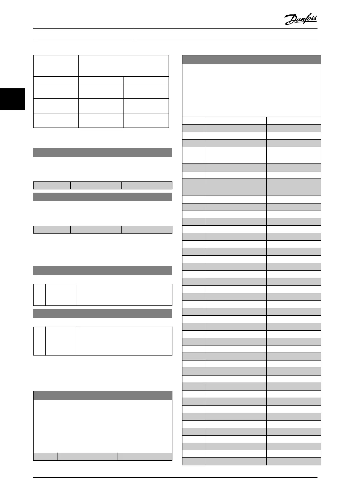
5-3* Digital Outputs
Setting in parameter 25-06 Number of
Pumps
[0] No [1] Yes
[200] Pump 1
Running
Controlled by
RELAY1
Frequency converter
controlled
[201] Pump 2
Running
Controlled by
RELAY2
Controlled by
RELAY1
[203] Pump 3
Running
Controlled by
RELAY3
Controlled by
RELAY2
Table 3.12 Settings
5-30 Terminal 27 Digital Output
This parameter has the options described in chapter 3.7.3 5-3*
Digital Outputschapter 3.7.4 5-3* Digital Outputs.
Option: Function:
[0] * No operation
5-31 Terminal 29 Digital Output
This parameter has the options described in chapter 3.7.3 5-3*
Digital Outputschapter 3.7.4 5-3* Digital Outputs.
Option: Function:
[0] * No operation
This parameter has the options described in
chapter 3.7.3 5-3* Digital Outputschapter 3.7.4 5-3* Digital
Outputs.
5-32 Term X30/6 Digi Out (MCB 101)
Option: Function:
[0] * No operation This parameter is active when option module
MCB 101 is mounted in the frequency
converter.
5-33 Term X30/7 Digi Out (MCB 101)
Option: Function:
[0] * No operation This parameter is active when option module
MCB 101 is mounted in the frequency
converter. Same options and functions as
parameter group 5-3* Digital Outputs.
3.7.4 5-4* Relays
Parameters for conguring the timing and the output
functions for the relays.
5-40 Function Relay
Array [8]
(Relay 1 [0], Relay 2 [1]
Option MCB 105: Relay 7 [6], Relay 8 [7] and Relay 9 [8]).
Select options to dene the function of the relays.
The selection of each mechanical relay is realised in an array
parameter.
Option: Function:
[0] No operation
5-40 Function Relay
Array [8]
(Relay 1 [0], Relay 2 [1]
Option MCB 105: Relay 7 [6], Relay 8 [7] and Relay 9 [8]).
Select options to dene the function of the relays.
The selection of each mechanical relay is realised in an array
parameter.
Option: Function:
[1] Control Ready
[2] Drive ready
[3] Drive rdy/rem ctrl
[4] Standby / no warning
[5] Running Default setting for relay
2.
[6] Running / no warning
[8] Run on ref/no warn
[9] Alarm Default setting for relay
1.
[10] Alarm or warning
[11] At torque limit
[12] Out of current range
[13] Below current, low
[14] Above current, high
[15] Out of speed range
[16] Below speed, low
[17] Above speed, high
[18] Out of feedb. range
[19] Below feedback, low
[20] Above feedback, high
[21] Thermal warning
[25] Reverse
[26] Bus OK
[27] Torque limit & stop
[28] Brake, no brake war
[29] Brake ready, no fault
[30] Brake fault (IGBT)
[31] Relay 123
[33] Safe stop active
[35] External Interlock
[36] Control word bit 11
[37] Control word bit 12
[40] Out of ref range
[41] Below reference, low
[42] Above ref, high
[45] Bus ctrl.
[46] Bus ctrl, 1 if timeout
[47] Bus ctrl, 0 if timeout
[60] Comparator 0
[61] Comparator 1
[62] Comparator 2
[63] Comparator 3
[64] Comparator 4
[65] Comparator 5
[70] Logic rule 0
Parameter Descriptions
VLT
®
HVAC Drive FC 102
76 Danfoss A/S © 03/2015 All rights reserved. MG11CE02
33
 Loading...


