4. Remove the alignment tool and install plug (D003); torque to 17 N•m [13 lbf•ft].
5. Replace the spring (D91) and spool plugs (D032 and D035).
6. Adjust control neutral (see Control neutral adjustment for MDC and EDC/HC-EDC on page 33).
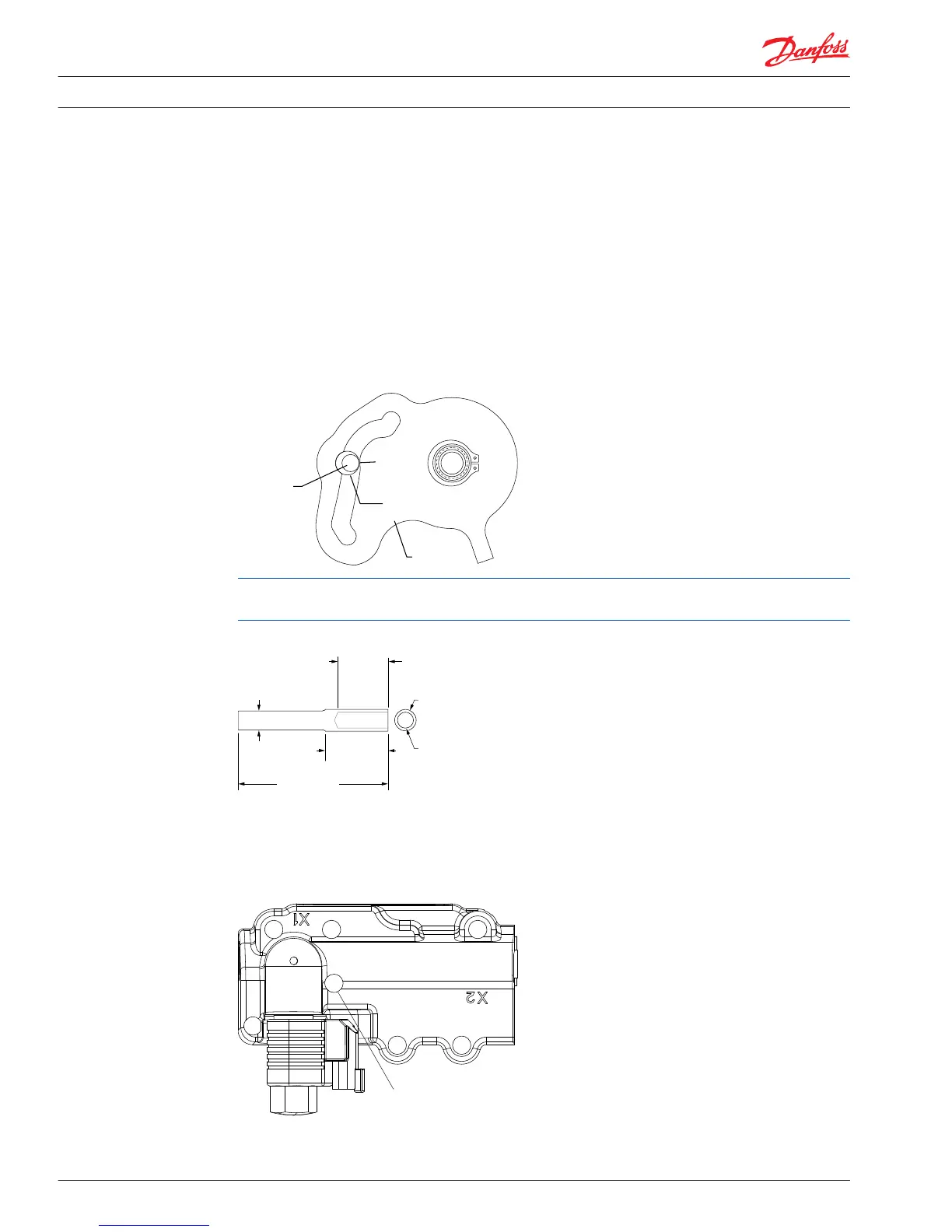
MDC alignment without tool.
If the MDC alignment tool is not available, it is possible to locate the approximate position of the pin by
creating an imaginary circle at the correct location, as indicated in the illustration. The point at which the
imaginary circle contacts the slot in the cam is the suggested contact point of the summing link pin.
When engaging the pin in the cam slot, you may need to use a flat tool, such as a screwdriver, to position
the linkage.
MDC cam
For proper control operation, the summing link must engage the slot on the control module. For exact
placement, use the alignment tool shown.
MDC alignment tool
3a. Install and hand-tighten the seven (7) control retaining screws and then back off each screw one turn.
Torque patterns (MDC, EDC and HC-EDC)
 Loading...


