Disassembly
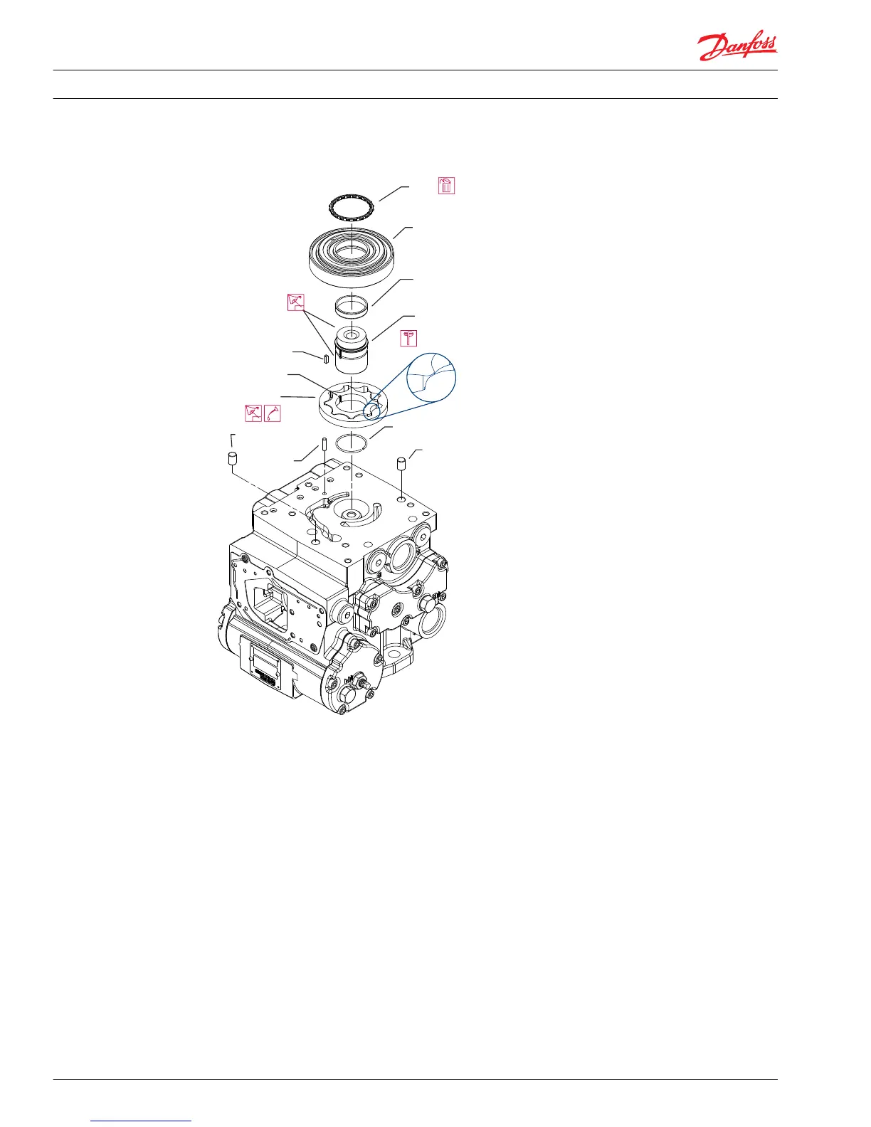
1. Remove alignment pins (U025)
2. Remove the gerotor cover assembly (G020). Remove and discard gerotor cover O-ring (G023) (early
production SAE A pad models may contain two or three seals: only the inner G023 seal is required).
3. Remove the drive coupling (U015) and gerotor gear set (G010). Remove retaining ring (G006).
4. Remove the gerotor drive pin or key (G005). Remove the gerotor cover locating pin (G065).
5. Inspect the gerotor assembly (G010). Ensure the upper and lower surfaces of the gerotor are free of
nicks and grooves. The mating surfaces of the inner and outer gears should fit snugly and create a
tight seal. Inspect the keyway for major wear. It is normal to find a small impression from the drive pin
(G005). Measure gerotor tip clearance for wear (illustrated above). Seat the gerotor assembly into the
gerotor cover and align the assembly so that one of the tips of the inner gear fully engages a valley in
the outer gear. Using a feeler gauge, measure the clearance of the opposite tip. Clearance should be
0.127 mm [0.005 inch] or less. Replace the gerotor if necessary. The gerotor assembly is machined as a
matched pair.
6. Inspect the drive pin or key (G005) to ensure that the edges are not rounded and that the drive
coupling’s internal splines are straight and free of damage on both ends. Check for wear on the top
and bottom surfaces. Replace the drive pin or key if worn.
7. Inspect the gerotor cover (G020). It should be free of nicks and scratches. The drive coupling journal
bearing (G015) is on the inside diameter of the small bore of the aluminum gerotor cover. The drive
Service Manual
Series 42 Axial Piston Closed Circuit Pumps
Minor Repair
58 520L0638 • Rev 0300 • July 2015
 Loading...


