NOTE
To comply with EMC emission specifications, screened/
armoured cables are recommended. If an unscreened/
unarmoured cable is used, see 4.6.13 Power and Control
Wiring for Unscreened Cables.
See 8 General Specifications for correct dimensioning of
motor cable cross-section and length.
Screening of cables:
Avoid installation with twisted screen ends (pigtails). They
spoil the screening effect at higher frequencies. If it is
necessary to break the screen to install a motor isolator or
motor contactor, the screen must be continued at the
lowest possible HF impedance.
Connect the motor cable screen to both the de-coupling
plate of the frequency converter and to the metal housing
of the motor.
Make the screen connections with the largest possible
surface area (cable clamp). This is done by using the
supplied installation devices within the frequency
converter.
Cable-length and cross-section:
The frequency converter has been EMC tested with a given
length of cable. Keep the motor cable as short as possible
to reduce the noise level and leakage currents.
Switching frequency:
When frequency converters are used together with Sine-
wave filters to reduce the acoustic noise from a motor, the
switching frequency must be set according to the
instruction in 14-01 Switching Frequency.
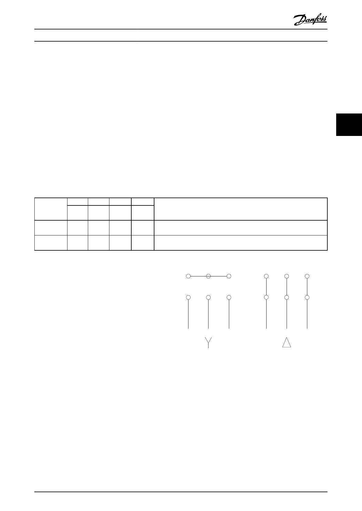
Term. no. 96 97 98 99
U V W
PE
1)
Motor voltage 0-100% of mains voltage.
3 wires out of motor
U1 V1 W1
PE
1)
Delta-connected
W2 U2 V2 6 wires out of motor
U1 V1 W1
PE
1)
Star-connected U2, V2, W2
U2, V2 and W2 to be interconnected separately.
Table 4.14
1)
Protected Earth Connection
NOTE
In motors without phase insulation paper or other
insulation reinforcement suitable for operation with
voltage supply (such as a frequency converter), fit a Sine-
wave filter on the output of the frequency converter.
U V W
175ZA114.10
VU W
96 97 98
96 97 98
Illustration 4.24
How to Install VLT Automation Low Harmonic Drive Operating Instructions
MG34O202 - VLT
®
is a registered Danfoss trademark 35
4 4
 Loading...


