3.3 Mounting
NOTICE!
Improper mounting can result in overheating and
reduced performance.
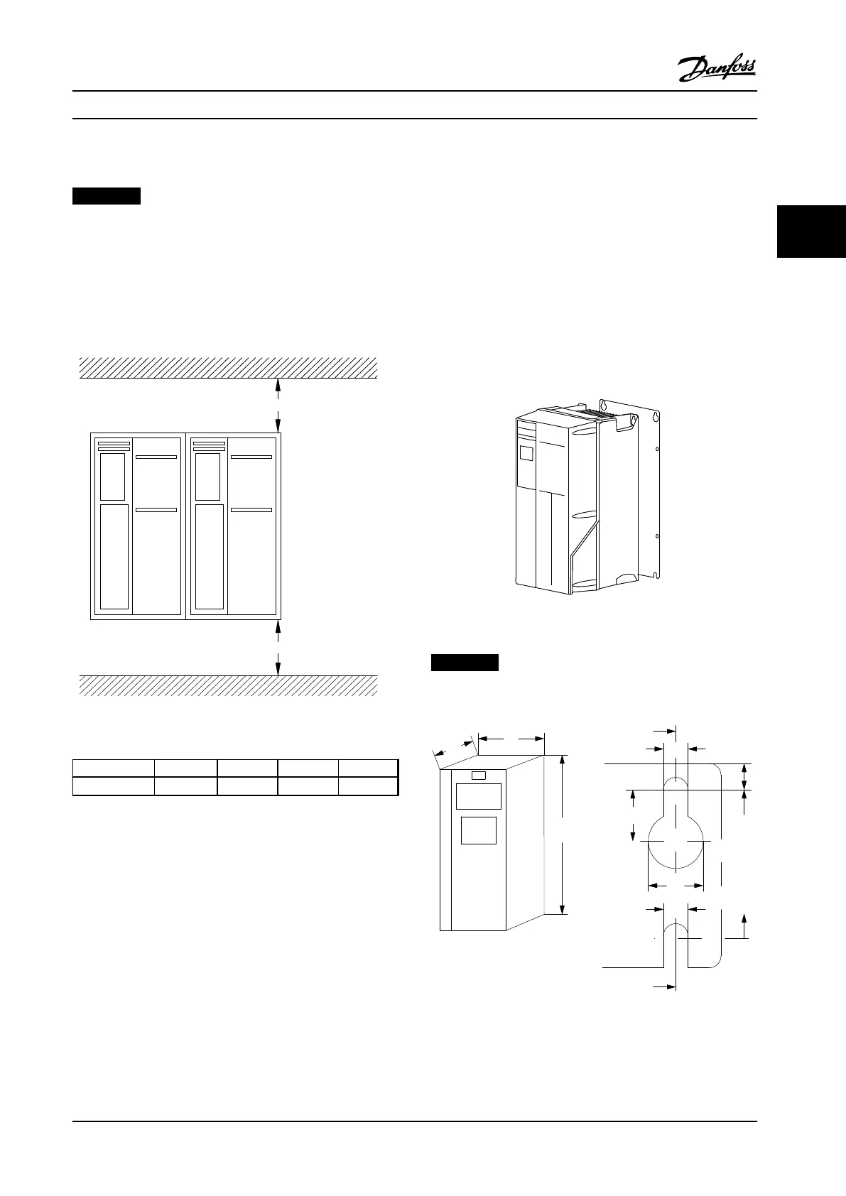
Cooling
•
Ensure that top and bottom clearance for air
cooling is provided. See Figure 3.2 for clearance
requirements.
Figure 3.2 Top and Bottom Cooling Clearance
Enclosure A1-A5 B1-B4 C1, C3 C2, C4
a (ins [mm]) 3.94 [100] 7.87 [200] 7.87 [200] 8.86 [225]
Table 3.1 Minimum Airflow Clearance Requirements
Lifting
•
To determine a safe lifting method, check the
weight of the unit, see chapter 8.9 Power Ratings,
Weight and Dimensions.
•
Ensure that the lifting device is suitable for the
task.
•
If necessary, plan for a hoist, crane, or forklift with
the appropriate rating to move the unit.
•
For lifting, use hoist rings on the unit, when
provided.
Mounting
1. Ensure that the strength of the mounting location
supports the unit weight. The adjustable
frequency drive allows side-by-side installation.
2. Place the unit as near to the motor as possible.
Keep the motor cables as short as possible.
3. Mount the unit vertically to a solid flat surface or
to the optional backplate to provide cooling
airflow.
4. Use the slotted mounting holes on the unit for
wall mounting, when provided.
Mounting with backplate and railings
Figure 3.3 Proper Mounting with Backplate
NOTICE!
Backplate is required when mounted on railings.
Figure 3.4 Top and Bottom Mounting Holes (See
chapter 8.9 Power Ratings, Weight and Dimensions)
Mechanical Installation Instruction Manual
MG33AP22 Danfoss A/S © Rev. 09/2014 All rights reserved. 11
3 3

 Loading...


