4.5 Access
•
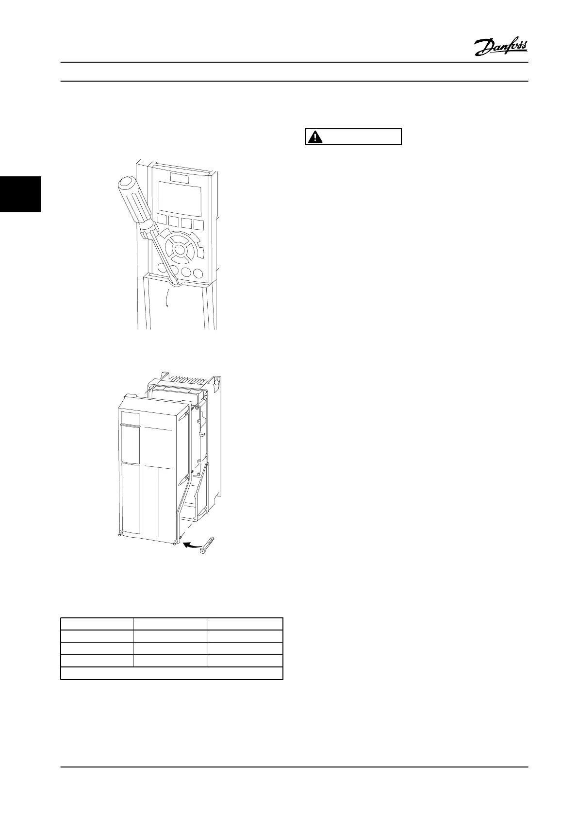
Remove cover with a screwdriver (See Figure 4.3)
or by loosening attaching screws (See Figure 4.4).
Figure 4.3 Access to Wiring for IP20 and IP21 Enclosures
Figure 4.4 Access to Wiring for IP55 and IP66 Enclosures
See
Table 4.1 before tightening covers.
Enclosure IP55 IP66
A4/A5 17.7 [2] 17.7 [2]
B1/B2 19.47 [2.2] 19.47 [2.2]
C1/C2 19.47 [2.2] 19.47 [2.2]
No screws to tighten for A1/A2/A3/B3/B4/C3/C4.
Table 4.1 Tightening Torques for Covers (in-lb [Nm])
4.6
Motor Connection
WARNING
INDUCED VOLTAGE
Induced voltage from output motor cables that run
together can charge equipment capacitors even with the
equipment turned off and locked out. Failure to run
output motor cables separately or use shielded cables or
metal conduits could result in death or serious injury.
•
Run output motor cables separately, or
•
Use shielded cables or metal conduits.
•
Comply with local and national electrical codes
for cable sizes. For maximum wire sizes, see
chapter 8.1 Electrical Data.
•
Follow the motor manufacturer wiring
requirements.
•
Motor wiring knockouts or access panels are
provided at the base of IP21 (NEMA1/12) and
higher units.
•
Do not wire a starting or pole-changing device
(e.g., Dahlander motor or slip ring induction
motor) between the adjustable frequency drive
and the motor.
Procedure
1. Strip a section of the outer cable insulation.
2. Position the stripped wire under the cable clamp
to establish mechanical fixation and electrical
contact between the cable shield and ground.
3. Connect the ground wire to the nearest
grounding terminal in accordance with the
grounding instructions provided in
chapter 4.3 Grounding, see Figure 4.5.
4. Connect the 3-phase motor wiring to terminals
96 (U), 97 (V), and 98 (W), see Figure 4.5.
5. Tighten the terminals in accordance with the
information provided in chapter 8.8 Connection
Tightening Torques.
Electrical Installation Instruction Manual
16 Danfoss A/S © Rev. 09/2014 All rights reserved. MG33AP22
44

 Loading...


