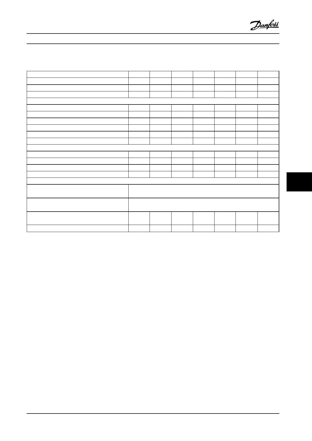
8.1.4 Line Power Supply 525–690 V (FC 302 only)
Type designation P1K1 P1K5 P2K2 P3K0 P4K0 P5K5 P7K5
High/Normal overload
1)
HO/NO HO/NO HO/NO HO/NO HO/NO HO/NO HO/NO
Typical shaft output (hp [kW]) 1.5 [1.1] 2 [1.5] 3 [2.2] 4 [3.0] 5 [4.0] 7.5 [5.5] 10 [7.5]
Enclosure protection rating IP20 A3 A3 A3 A3 A3 A3 A3
Output current
Continuous (525–550 V) [A] 2.1 2.7 3.9 4.9 6.1 9.0 11.0
Intermittent (525–550 V) [A] 3.4 4.3 6.2 7.8 9.8 14.4 17.6
Continuous (551–690 V) [A] 1.6 2.2 3.2 4.5 5.5 7.5 10.0
Intermittent (551–690 V) [A] 2.6 3.5 5.1 7.2 8.8 12.0 16.0
Continuous KVA 525 V 1.9 2.5 3.5 4.5 5.5 8.2 10.0
Continuous KVA 690 V 1.9 2.6 3.8 5.4 6.6 9.0 12.0
Maximum input current
Continuous (525–550 V) [A] 1.9 2.4 3.5 4.4 5.5 8.1 9.9
Intermittent (525–550 V) [A] 3.0 3.9 5.6 7.0 8.8 12.9 15.8
Continuous (551–690 V) [A] 1.4 2.0 2.9 4.0 4.9 6.7 9.0
Intermittent (551–690 V) [A] 2.3 3.2 4.6 6.5 7.9 10.8 14.4
Additional specifications
Maximum cable cross-section
2)
for line power, motor,
brake and load sharing [mm
2
] ([AWG])
4, 4, 4 (12, 12, 12) (min. 0.2 (24)
Maximum cable cross-section
2)
for disconnect
[mm
2
] ([AWG])
6, 4, 4 (10, 12, 12)
Estimated power loss at rated maximum load (hp
[W])
3)
0.059 [44] 0.081 [60] 0.118 [88]
0.161
[120]
0.215
[160]
0.295
[220]
0.402
[300]
Efficiency
4)
0.96 0.96 0.96 0.96 0.96 0.96 0.96
Table 8.10 A3 Enclosure, Line Power Supply 525–690 V IP20/Protected Chassis, P1K1-P7K5
Specifications Instruction Manual
MG33AP22 Danfoss A/S © Rev. 09/2014 All rights reserved. 61
8 8

 Loading...


