4.8.1 Control Terminal Types
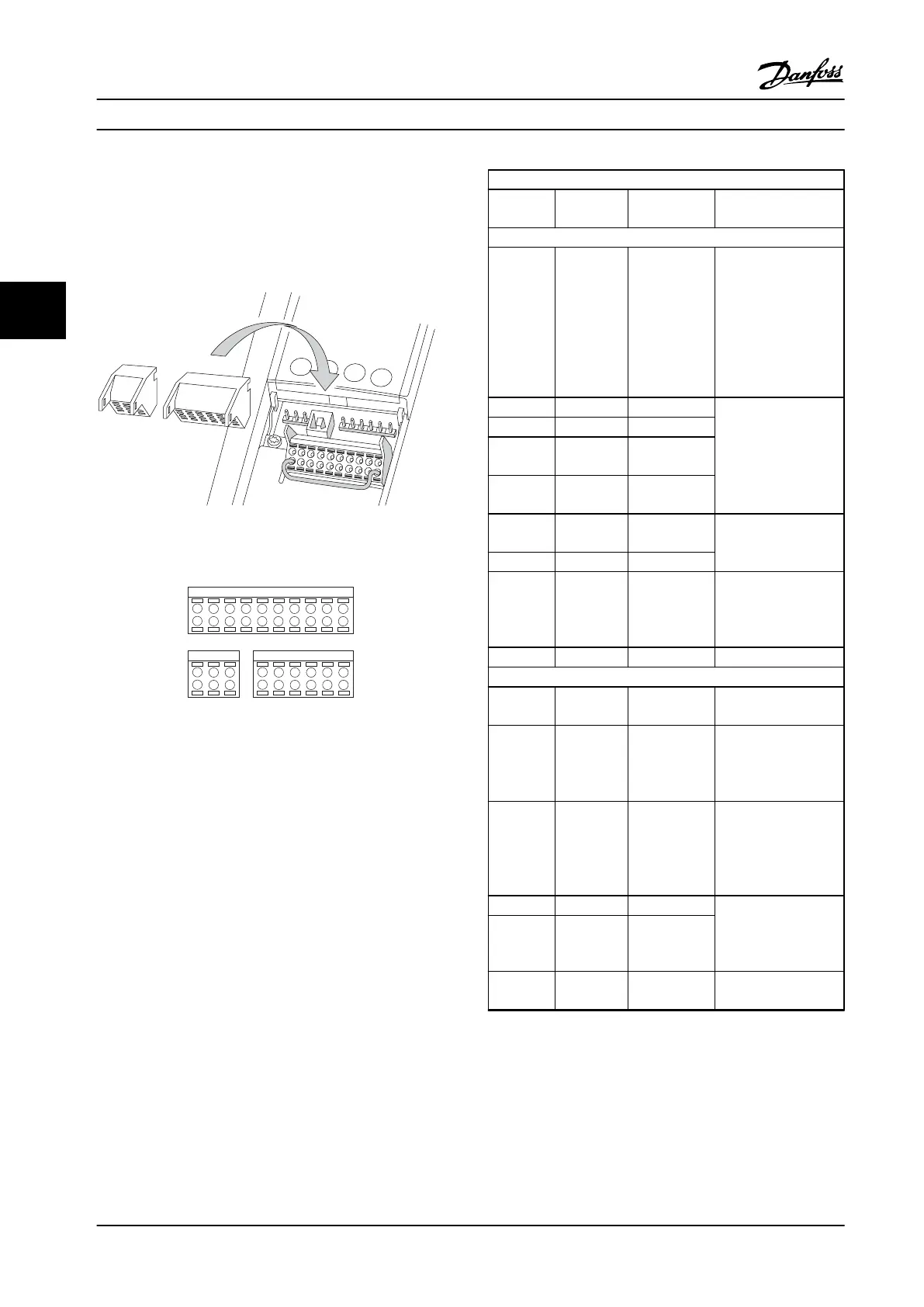
Figure 4.7 and Figure 4.8 show the removable adjustable
frequency drive connectors. Terminal functions and default
settings are summarized in Table 4.2 and Table 4.3.
Figure 4.7 Control Terminal Locations
12 13 18 19 27 29 32 33 20 37
39 42 50 53 54 55
61 68 69
130BB931.10
1
2 3
Figure 4.8 Terminal Numbers
•
Connector 1 provides four programmable digital
inputs terminals, two additional digital terminals
programmable as either input or output, a 24 V
DC terminal supply voltage, and a common for
optional customer supplied 24 V DC voltage. FC
302 and FC 301 (optional in A1 enclosure) also
provide a digital input for STO function
•
Connector 2 terminals (+)68 and (-)69 for RS-485
serial communication connection
•
Connector 3 provides two analog inputs, one
analog output, 10 V DC supply voltage, and
commons for the inputs and output
•
Connector 4 is a USB port available for use with
the MCT 10 Set-up Software
Terminal description
Terminal Parameter Default
setting
Description
Digital inputs/outputs
12, 13 - +24 V DC 24 V DC supply
voltage for digital
inputs and external
transducers. Maximum
output current
200 mA (130 mA for
FC 301) for all 24 V
loads.
18 5-10 [8] Start Digital inputs.
19 5-11 [10] Reversing
32 5-14 [0] No
operation
33 5-15 [0] No
operation
27 5-12 [2] Coast
inverse
For digital input or
output. Default setting
is input.
29 5-13 [14] JOG
20 - Common for digital
inputs and 0 V
potential for 24 V
supply.
37 - STO Safe input.
Analog inputs/outputs
39 - Common for analog
output.
42 6-50 [0] No
operation
Programmable analog
output. 0-20 mA or
4-20 mA at a
maximum of 500 Ω
50 - +10 V DC 10 V DC analog
supply voltage for
potentiometer or
thermistor. 15 mA
maximum
53 6-1* Reference Analog input. For
voltage or current.
Switches A53 and A54
select mA or V.
54 6-2* Feedback
55 - Common for analog
input.
Table 4.2 Terminal Description Digital Inputs/Outputs,
Analog Inputs/Outputs
Electrical Installation
Instruction Manual
18 Danfoss A/S © Rev. 09/2014 All rights reserved. MG33AP22
44
 Loading...


