9 Appendix
9.1 Symbols, Abbreviations and Conventions
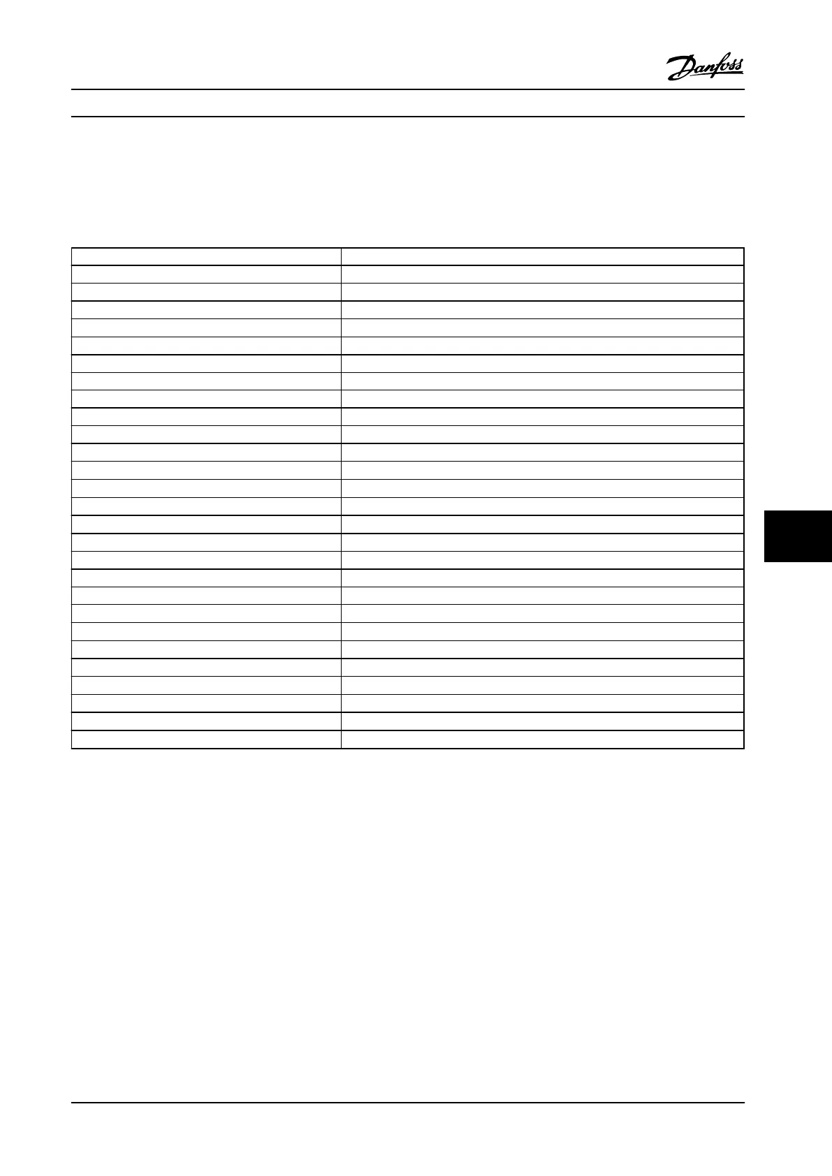
AC Alternating current
AEO Automatic energy optimization
AWG American wire gauge
AMA Automatic motor adaptation
°C
Degrees celsius
DC Direct current
EMC Electro magnetic compatibility
ETR Electronic thermal relay
FC Adjustable frequency drive
LCP Local control panel
MCT Motion control tool
IP Ingress protection
I
M,N
Nominal motor current
f
M,N
Nominal motor frequency
P
M,N
Nominal motor power
U
M,N
Nominal motor voltage
PM Motor Permanent magnet motor
PELV Protective extra low voltage
PCB Printed circuit board
PWM Pulse width modulated
I
LIM
Current limit
I
INV
Rated inverter output current
RPM Revolutions per minute
Regen Regenerative terminals
n
s
Synchronous motor speed
T
LIM
Torque limit
I
VLT,MAX
Maximum output current
I
VLT,N
Rated output current supplied by the adjustable frequency drive
Table 9.1 Symbols and Abbreviations
Conventions
Numbered lists indicate procedures.
Bullet lists indicate other information and description of figures.
Italicized text indicates:
•
Cross reference
•
Link
•
Parameter name
All dimensions are in (in [mm]).
9.2
Parameter Menu Structure
Appendix Instruction Manual
MG33AP22 Danfoss A/S © Rev. 09/2014 All rights reserved. 79
9 9

 Loading...


