NOTICE!
POTENTIAL EQUALIZATION
Risk of electrical interference, when the ground potential between the adjustable frequency drive and the control
system is different. Install equalizing cables between the system components. Recommended cable cross-section: AWG 6
[16 mm
2
].
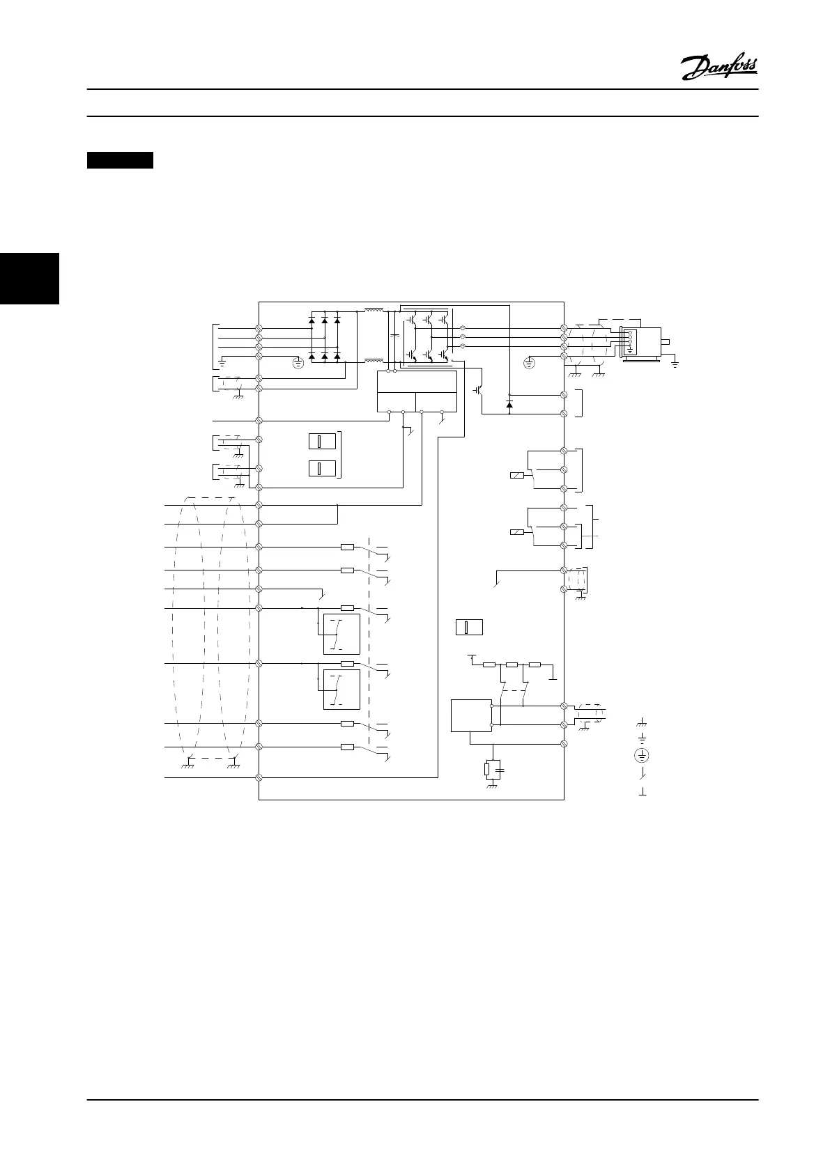
4.4 Wiring Schematic
130BD599.11
3-phase
power
input
DC bus
Switch Mode
Power Supply
Motor
Analog Output
Interface
relay1
relay2
ON=Terminated
OFF=Open
Brake
resistor
91 (L1)
92 (L2)
93 (L3)
PE
88 (-)
89 (+)
50 (+10 V OUT)
53 (A IN)
54 (A IN)
55 (COM A IN)
0/4-20 mA
12 (+24 V OUT)
13 (+24 V OUT)
37 (D IN)
18 (D IN)
20 (COM D IN)
10 V DC
15 mA 130/200 mA
+ - + -
(U) 96
(V) 97
(W) 98
(PE) 99
(COM A OUT) 39
(A OUT) 42
(P RS-485) 68
(N RS-485) 69
(COM RS-485) 61
0 V
5V
S801
0/4-20 mA
RS-485
RS-485
03
+10 V DC
0/-10 V DC -
+10 V DC
+10 V DC
0/4-20 mA
0/-10 V DC-
240 V AC, 2 A
24 V DC
02
01
05
04
06
24 V (NPN)
0 V (PNP)
0 V (PNP)
24 V (NPN)
19 (D IN)
24 V (NPN)
0 V (PNP)
27
24 V
0 V
(D IN/OUT)
0 V (PNP)
24 V (NPN)
(D IN/OUT)
0 V
24 V
29
24 V (NPN)
0 V (PNP)
0 V (PNP)
24 V (NPN)
33 (D IN)
32 (D IN)
1 2
ON
S201
ON
21
S202
ON=0/4-20 mA
OFF=0/-10 V DC -
+10 V DC
95
P 5-00
21
ON
S801
(R+) 82
(R-) 81
: Chassis
**
240 V AC, 2 A
400 V AC, 2 A
*
*
*
: Ground
: Ground 1
: Ground 2
: PE
Figure 4.1 Basic Wiring Schematic
A=Analog, D=Digital
*Terminal 37 (optional) is used for Safe Torque Off (STO). For installation instructions, refer to the VLT
®
Safe Torque Off
Instruction Manual. Terminal 37 is not included in FC 301 (except enclosure type A1). Relay 2 and terminal 29 have no
function in FC 301.
**Do not connect cable shield.
Electrical Installation
Instruction Manual
14 Danfoss A/S © Rev. 09/2014 All rights reserved. MG33AP22
44

 Loading...


