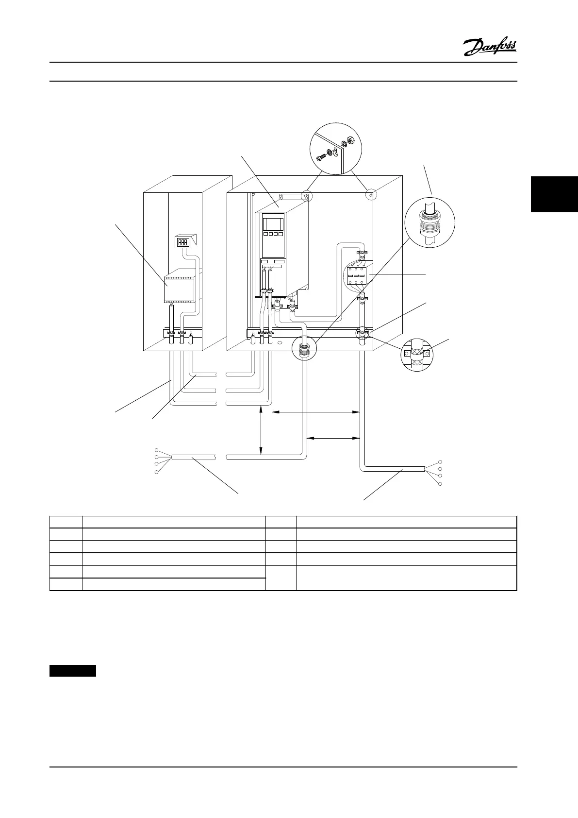
1 PLC 7 Motor, 3--phase and PE (shielded)
2 Adjustable frequency drive 8 Line power, 3--phase and reinforced PE (non-shielded)
3 Output contactor 9 Control wiring (shielded)
4 Cable clamp 10
Potential equalization min. AWG 6 [16 mm
2
]
5 Cable insulation (stripped)
11
Clearance between control cable, motor cable and line cable:
Min. 7.9 in [200 mm]
6 Cable connector
Figure 4.2 EMC-compliant Electrical Connection
For more information about EMC, see chapter 4.2 EMC-compliant Installation
NOTICE!
EMC INTERFERENCE
Run cables for input power, motor wiring and control wiring in three separate metallic conduits. Failure to isolate
power, motor and control cables can result in unintended behavior or reduced performance. Minimum 7.9 in [200 mm]
clearance between power, motor and control cables is required.
Electrical Installation Instruction Manual
MG33AP22 Danfoss A/S © Rev. 09/2014 All rights reserved. 15
4 4
 Loading...


