4.12.4 13-4* Logic Rules
Combine up to 3 boolean inputs (true/false inputs) from
timers, comparators, digital inputs, status bits, and events
using the logical operators AND, OR, and NOT. Select
boolean inputs for the calculation in parameter 13-40 Logic
Rule Boolean 1, parameter 13-42 Logic Rule Boolean 2, and
parameter 13-44 Logic Rule Boolean 3. Dene the operators
used to logically combine the selected inputs in
parameter 13-41 Logic Rule Operator 1 and
parameter 13-43 Logic Rule Operator 2.
. . .
. . .
. . .
. . .
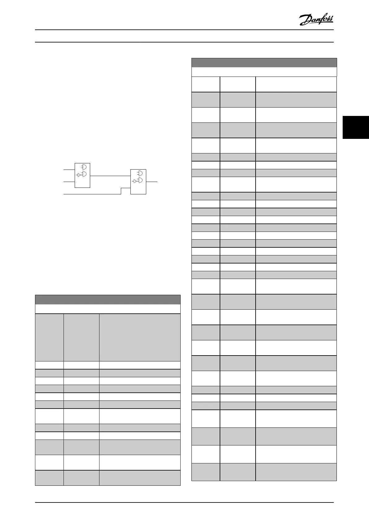
Par. 13-43
Logic Rule Operator 2
Par. 13-41
Logic Rule Operator 1
Par. 13-40
Logic Rule Boolean 1
Par. 13-42
Logic Rule Boolean 2
Par. 13-44
Logic Rule Boolean 3
130BB673.10
Illustration 4.39 Logic Rules
Priority of calculation
The results of parameter 13-40 Logic Rule Boolean 1,
parameter 13-41 Logic Rule Operator 1, and
parameter 13-42 Logic Rule Boolean 2 are calculated rst.
The outcome (true/false) of this calculation is combined
with the settings of parameter 13-43 Logic Rule Operator 2
and parameter 13-44 Logic Rule Boolean 3, yielding the nal
result (true/false) of the logic rule.
13-40 Logic Rule Boolean 1
Option: Function:
[0] False Select the rst boolean (true or
false) input for the selected logic
rule.
See parameter 13-01 Start Event and
parameter 13-02 Stop Event for more
information.
[1] True
[2] Running
[3] In range
[4] On reference
[5] Torque limit
[6] Current Limit
[7] Out of current
range
[8] Below I low
[9] Above I high
[10] Out of speed
range
[11] Below speed
low
[12] Above speed
high
13-40 Logic Rule Boolean 1
Option: Function:
[13] Out of feedb.
range
[14] Below feedb.
low
[15] Above feedb.
high
[16] Thermal
warning
[17] Mains out of
range
[18] Reversing
[19] Warning
[20] Alarm (trip)
[21] Alarm (trip
lock)
[22] Comparator 0
[23] Comparator 1
[24] Comparator 2
[25] Comparator 3
[26] Logic rule 0
[27] Logic rule 1
[28] Logic rule 2
[29] Logic rule 3
[30] SL Time-out 0
[31] SL Time-out 1
[32] SL Time-out 2
[33] Digital input
DI18
[34] Digital input
DI19
[35] Digital input
DI27
[36] Digital input
DI29
[37] Digital input
DI32
[38] Digital input
DI33
[39] Start
command
[40] Drive stopped
[41] Reset Trip
[42] Auto-reset Trip
[43] Ok key [OK] is pressed. Only available on
the graphical LCP.
[44] Reset key [Reset] is pressed. Only available on
the graphical LCP.
[45] Left key
[◄] is pressed. Only available on the
graphical LCP.
[46] Right key
[►] is pressed. Only available on the
graphical LCP.
Parameter Descriptions Programming Guide
MG06J202 Danfoss A/S © 03/2019 All rights reserved. 121
4 4
 Loading...


