4.2.6 1-6* Load Depend. Setting
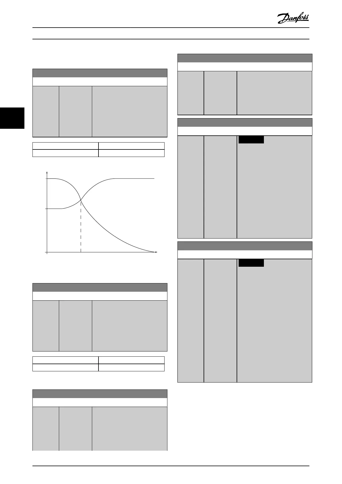
1-60 Low Speed Load Compensation
Range: Function:
100 %* [0 - 300 %] Enter the % value to compensate
voltage in relation to load when the
motor is running at low speed and
obtain the optimum U/f charac-
teristic. The motor size determines
the frequency range within which
this parameter is active.
Motor size Changeover
0.25–7.5 kW <10 Hz
130BA046.11
60%
0%
100%
U
m
Changeover
f
out
Par.1-60 Par.1-61
Illustration 4.8 Changeover
1-61 High Speed Load Compensation
Range: Function:
100 %* [0 - 300 %] Enter the % value to compensate
voltage in relation to load when the
motor is running at high speed and
obtain the optimum U/f charac-
teristic. The motor size determines
the frequency range within which
this parameter is active.
Motor size Changeover
0.25–7.5 kW >10 Hz
Table 4.4 Changeover Frequency
1-62 Slip Compensation
Range: Function:
Size
related*
[-500 -
500 %]
Enter the % value for slip compen-
sation to compensate for tolerances
in the value of n
M,N
. Slip compen-
sation is calculated automatically,
that is on the basis of the nominal
motor speed n
M,N
.
1-62 Slip Compensation
Range: Function:
This function is not active when
parameter 1-00 Conguration Mode
is set to [1] Speed closed loop or
when parameter 1-01 Motor Control
Principle is set to [0] U/f special
motor mode.
1-63 Slip Compensation Time Constant
Range: Function:
Size
related*
[0.05 - 5 s]
NOTICE
Parameter 1-63 Slip Compen-
sation Time Constant has no
eect when
parameter 1-10 Motor
Construction = [1] PM, non-
salient SPM.
Enter the slip compensation
reaction speed. A high value results
in slow reaction, and a low value
results in quick reaction. If low-
frequency resonance problems
arise, use a longer time setting.
1-64 Resonance Damping
Range: Function:
Size
related*
[0 - 1000 %]
NOTICE
Parameter 1-64 Resonance
Dampening has no eect when
parameter 1-10 Motor
Construction = [1] PM, non-
salient SPM.
Enter the resonance damping value.
Set parameter 1-64 Resonance
Dampening and
parameter 1-65 Resonance
Dampening Time Constant to help
eliminate high frequency resonance
problems. To reduce resonance
oscillation, increase the value of
parameter 1-64 Resonance
Dampening.
Parameter Descriptions VLT® AutomationDrive FC 361
42 Danfoss A/S © 03/2019 All rights reserved. MG06J202
44
 Loading...


