14-22 Operation Mode
Option: Function:
3. Set switches S201 (A53) and S202
(A54) = ON./I.
4. Insert the test plug (see below).
5. Connect to mains supply.
6. Carry out various tests.
7. The results are displayed on the LCP
and the frequency converter moves
into an innite loop.
8. Parameter 14-20 Reset Mode is
automatically set to Normal operation.
Carry out a power cycle to start up in
Normal operation after a control card
test.
If the test is OK:
LCP read-out: Control Card OK.
Disconnect the mains supply and remove the
test plug. The green LED on the Control Card
will light up.
If the test fails:
LCP read-out: Control Card I/O failure.
Replace the frequency converter or Control card.
The red LED on the Control Card is turned on.
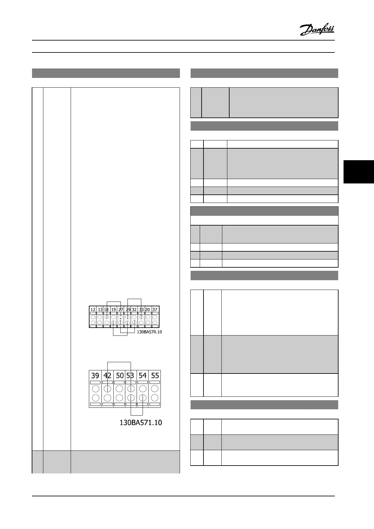
Test plugs (connect the following terminals to
each other): 18 - 27 - 32; 19 - 29 - 33; 42 - 53 -
54 1.
Figure 6.19
Figure 6.20
[2] initiali-
zation
Resets all parameter values to default settings,
except for parameter 15-03 Power Up's,
parameter 15-04 Over Temp's and
14-22 Operation Mode
Option: Function:
parameter 15-05 Over Volt's. The frequency
converter will reset during the next power-up.
Parameter 14-20 Reset Mode will also revert to
the default setting [0] Normal operation.
14-52 Fan Control
Option: Function:
Select the minimum speed of the internal fan.
[0] * Auto Runs the fan only when the internal temperature
of the frequency converter is in the range 35 °C .
approx. 55 °C. The fan will run at low speed at
35 °C, and at full speed at approx. 55 °C.
[1] On 50%
[2] On 75%
[3] On 100%
14-53 Fan Monitor
Option: Function:
Select which reaction the frequency converter
should take in case a fan fault is detected.
[0] Disabled
[1] Warning
[2] Trip
14-60 Function at Over Temperature
Option: Function:
If either heatsink or control card temperature
exceeds a factory-programmed temperature limit, a
warning will be activated. If the temperature
increases further, select whether the frequency
converter should trip (trip locked) or derate the
output current.
[0] Trip The frequency converter will trip (trip locked) and
generate an alarm. Power must be cycled to reset
the alarm, but will not allow restart of the motor
until the heat sink temperature has dropped below
the alarm limit.
[1] * Derate If the critical temperature is exceeded the output
current will be reduced until the allowable
temperature has been reached.
14-61 Function at Inverter Overload
Option: Function:
Is used in case of steady overload beyond the
thermal limits (110% for 60 sec.).
[0] Trip The frequency converter trips and provides an
alarm.
[1] * Derate Reduce pump speed to decrease the load on the
power section and allowing this to cool down.
Parameter Descriptions Operating Instructions
MG34M422 Danfoss A/S © Rev. 2013-07-03 All rights reserved. 103
6
6

 Loading...


